
ZYPLC Blog
SINUMERIK Measuring Circuit Faults
Troubleshoot SINUMERIK measuring-circuit alarms by separating encoder, cable, interface and drive causes before a CNC restart or spare order.
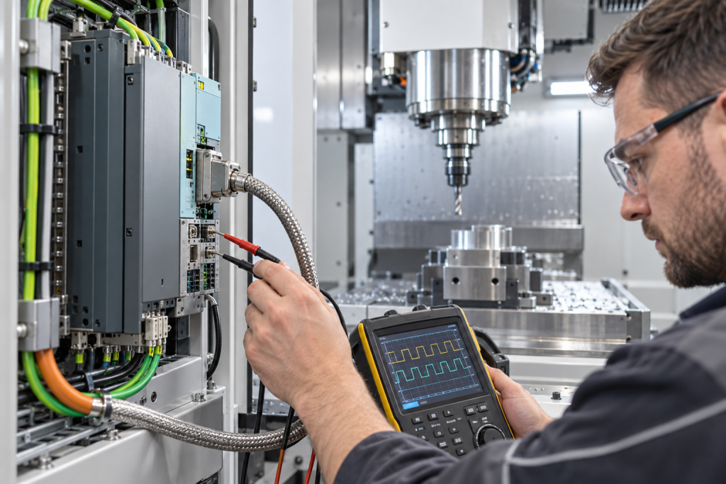
A CNC axis that loses position reference, reports an encoder alarm or refuses to enable is easy to describe as a failed measuring-circuit module. The same symptom can come from encoder supply, damaged shield termination, connector contamination, feedback configuration, motor coupling or the interface itself. In a machine tool, substituting electronics without preserving the axis and reference data can create a second failure: a powered axis whose position is no longer trustworthy.
Start by treating the feedback loop as a chain from the mechanical encoder through cable and interface to drive and CNC diagnostics. The Siemens 6FC5111-0BA01-0AA0 appears in the site catalog as a measuring-circuit module; the product URL title uses generic interface wording, so the complete nameplate and installed role must be checked before any compatibility claim.
Protect the machine state first
Record the alarm text and number, axis, machine mode, position, last reference event, speed, load, temperature and whether the fault appears at power-up or only after movement. Save the CNC diagnostics and project or machine backup using the approved method. Mark the axis as unavailable and follow the machine builder’s safe state procedure; do not repeatedly acknowledge an encoder fault and command motion in an attempt to make it disappear.
Photograph the module label, connector face, cable route, motor and encoder labels, axis cabinet location and any adapter or junction box. Record encoder technology, resolution, supply, interface format, connector pinout, cable length, shield bonding and installed firmware. On older equipment, the as-built configuration may differ from the original machine manual; reconcile before changing parameters.
Inspect the feedback path from end to end
With isolation applied, inspect the encoder connector for bent pins, oil, coolant, metal dust, damaged keying, loose coupling and strain. Check cable jacket abrasion, tight bend radii, crushed sections, drag-chain wear, shield continuity and grounding at the specified end points. A short intermittent break can appear only at a particular axis position or during acceleration, so correlate physical flex points with event timing.
Verify encoder supply and signal only with the machine builder’s approved method and suitable instruments. Compare expected differential or single-ended levels, phase relationship, reference marker and termination to the installed encoder specification. Do not use a generic continuity test as proof of a high-speed feedback cable. Record the test setup and whether the cable was disconnected from sensitive electronics.
Use diagnostics to distinguish signal from configuration
Compare raw count, actual position, speed feedback, marker status and channel quality with the known machine baseline. If the count is stable at standstill but becomes noisy during motion, suspect cable routing, shielding, connector or vibration before concluding that the measuring board is defective. If the signal is clean but scale or direction is wrong, review configuration, encoder resolution, motor data and axis assignment instead of exchanging hardware.
Check whether the alarm follows one channel, one connector or the axis after controlled isolation and approved cross-checks. Never swap feedback connections between axes unless the procedure explicitly permits it and safe motion is prevented. A reversible test with a documented rollback is more useful than changing several modules and parameters at once.
Qualify the candidate module and control unit
For a suspected module issue, the Siemens 6FC5111-0BA01-0AA0 measuring-circuit module should be matched against the complete order number, revision, channel type, machine configuration, connectors and engineering-system version. Confirm the module’s installed function from the machine documentation; a catalog title alone does not prove it is the failed feedback component.
The drive control boundary may also matter. A Siemens 6SL3040-1MA01-0AA0 SINAMICS S120 control unit is not interchangeable with a measuring circuit simply because both participate in axis diagnostics. Keep distinct fault hypotheses and request that any offered spare identify hardware revision, firmware, test method, accessories and the exact unit to ship.
Re-reference and prove the axis deliberately
After repair, confirm the machine backup and parameter comparison, encoder direction, actual-value scaling, reference marker behavior and axis limits before enabling production motion. Follow the builder’s procedure for homing or referencing; absolute encoders, incremental encoders and direct measuring systems have different recovery requirements. Have a qualified person validate the machine coordinate relationship against a known datum.
Run a staged acceptance: static diagnostics, low-speed movement in a safe region, repeatability check, representative travel, following-error observation and machine-builder-defined accuracy test. Verify interlocks, tool or workpiece clearance, alarms and safe stop behavior. Record as-left module and encoder identities, values, test path, measurement uncertainty and operator signoff before returning the axis to service.
Questions Maintenance Teams Ask
Does an encoder alarm prove that the feedback module failed?
No. Encoder supply, cable, connector, shielding, parameters, mechanical coupling and interface hardware can cause similar symptoms. Isolate them with machine-approved tests.
Can I swap measuring-circuit modules between axes?
Only if the machine builder and controls procedure explicitly permit it, configurations are preserved and motion is inhibited. A blind swap can invalidate axis data or create a hazard.
What should I include in a SINUMERIK spare request?
Provide the complete 6FC number and revision, machine model, installed function, encoder and cable details, connector photos, software context and required acceptance evidence.
What proves an axis is ready after repair?
Stable feedback, correct scaling and direction, verified reference behavior, safe staged motion, repeatability and machine-specific acceptance checks.
Send ZYPLC the complete SINUMERIK and measuring-module labels, CNC alarm history, encoder and cable markings, cabinet photos, machine model, backup status and recovery deadline. We can help identify the correct catalog item and information needed for a focused inquiry.
© 2026 ZYPLC. All rights reserved. Official Website: https://zyplc.com Inquiry: sales@zyplc.com | WhatsApp/Tel: +86 18359293191