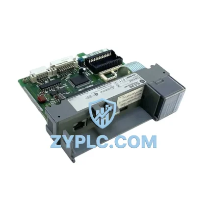
Allen-Bradley 1336-BDB-SP4D System-Ready Gate Drive for 1336 Architecture
The Allen-Bradley 1336-BDB-SP4D (Part No. 74103-244-54) is a precision-engineered Gate Drive PCB Assembly designed as a core switching control component within the Allen-Bradley 1336 PLUS and 1336 IMPACT AC drive platform. In modern industrial automation, the reliability of a variable frequency drive system depends not only on the quality of its individual modules but on the coherence of the entire control architecture — from the CPU and I/O layers down through the power conversion and gate switching stages. The 1336-BDB-SP4D occupies a critical position in this hierarchy, directly governing IGBT firing sequences and ensuring that the power stage responds with precision to commands issued from the drive’s control board.
Unlike generic replacement components, the 1336-BDB-SP4D is engineered for full contextual integration within the 1336 drive family. It interfaces seamlessly with the 1336-BDB main control board, the 1336-MOD-HA2 communication adapter, and the 1336-GM6 gate module assembly, maintaining signal integrity across the full operating range of the drive. This level of Contextual Integration ensures that the gate drive does not introduce timing errors, voltage spikes, or EMI anomalies that could propagate upstream to the PLC or SCADA layer.
Architecture Specification Table
| Parameter |
Specification |
| Part Number |
1336-BDB-SP4D / 74103-244-54 |
| Brand |
Allen-Bradley (Rockwell Automation) |
| Series |
1336 PLUS / 1336 IMPACT AC Drive |
| Product Type |
Gate Drive PCB Assembly |
| System Role |
IGBT Gate Switching Control — Power Stage Interface |
| Electrical Interface |
Low-voltage gate signal input; isolated high-voltage IGBT drive output |
| Communication Compatibility |
Internal drive bus; compatible with 1336-MOD-HA2 (DH+/RIO) adapter |
| Installation Environment |
Enclosed drive chassis; DIN-rail or panel-mount drive enclosure |
| Operating Temperature |
0°C to +55°C (drive enclosure ambient) |
| Humidity |
5% to 95% non-condensing |
| Origin |
United States (Rockwell Automation) |
| Warranty |
12-Month Warranty — covers manufacturing defects and functional failure under normal operating conditions |
Coordinated Control System Design
The 1336-BDB-SP4D does not function in isolation — it is one node in a tightly coordinated drive architecture. In a typical 1336-series drive installation, the system begins at the control layer with a ControlLogix or SLC 500 PLC issuing speed and torque references via a DeviceNet or Remote I/O network. These commands are received by the 1336-MOD-HA2 communication adapter, which translates network commands into internal drive references consumed by the 1336-BDB main control board.
The main control board processes the reference signal and generates PWM gate commands, which are then passed to the 1336-BDB-SP4D Gate Drive PCB. The gate drive amplifies and isolates these signals before delivering them to the IGBT power modules in the 1336-GM6 gate module assembly. The power stage then converts DC bus voltage — supplied through the 1336-BDB-SP4D-compatible rectifier and DC bus capacitor bank — into the variable-frequency AC output that drives the motor.
Supporting this architecture are several additional components that must be considered during system design and maintenance planning. The 1336-L6E power supply module provides regulated low-voltage DC to the control and gate drive boards, and its health directly affects the stability of the 1336-BDB-SP4D’s operation. The 1336-BDB-SP4D also works in conjunction with the 1336-BDB-SP2 snubber board, which suppresses voltage transients at the IGBT collector-emitter junctions during switching events.
For installations requiring redundancy, the 1336 platform supports bypass configurations using the 1336-BCB bypass control board, allowing the motor to continue operating on line power if the drive trips. In such architectures, the gate drive PCB must be maintained in a known-good state to ensure rapid drive restoration after a bypass event. Stocking a verified replacement 1336-BDB-SP4D — covered under a 12-Month Warranty — is a standard practice in high-availability process lines.
At the human-machine interface layer, PanelView 800 or PanelView Plus terminals connected via EtherNet/IP or DH+ provide operators with real-time drive status, fault codes, and parameter access. Fault data generated by the 1336-BDB-SP4D — such as gate drive fault (F12) or IGBT overcurrent — is surfaced at the HMI and logged by the ControlLogix historian for predictive maintenance analysis.
Application in Layered Automation Systems
The Allen-Bradley 1336-BDB-SP4D Gate Drive PCB finds application across a broad range of industrial sectors where the 1336 PLUS and 1336 IMPACT drive platforms remain in active service.
In manufacturing and packaging lines, 1336-series drives control conveyor motors, indexing tables, and winding machines. The gate drive PCB is subject to frequent start-stop cycles and must maintain switching accuracy across thousands of daily operations. A failed gate drive in this environment causes immediate production stoppage, making rapid replacement with a warranted component essential.
In water and wastewater treatment facilities, 1336 drives manage pump and blower motors operating continuously at variable loads. The 1336-BDB-SP4D must withstand high ambient humidity and temperature cycling. Facilities typically maintain one or two spare gate drive assemblies per critical pump station to meet regulatory uptime requirements.
In oil, gas, and petrochemical processing, drives installed in hazardous-area control panels depend on the gate drive PCB for precise motor control in compressor and agitator applications. The Contextual Integration of the 1336-BDB-SP4D within the existing 1336 platform eliminates the need for drive replacement, preserving the existing safety interlock and emergency shutdown wiring.
In mining and metallurgical operations, 1336 drives power crusher motors, ball mill drives, and conveyor systems. These applications demand robust gate switching performance under high-inertia load conditions. The 1336-BDB-SP4D’s compatibility with the 1336-GM6 gate module ensures that IGBT firing remains synchronized even under asymmetric load conditions.
In power generation and utilities, 1336-series drives are used in cooling tower fan control, boiler feed pump drives, and auxiliary motor control centers. Planned maintenance intervals in these facilities align with the 12-Month Warranty period, allowing engineering teams to schedule gate drive inspections and replacements without unplanned outages.
Architecture Engineering FAQ
Q1: Is the 1336-BDB-SP4D compatible with both the 1336 PLUS and 1336 IMPACT drive variants?
The 1336-BDB-SP4D (74103-244-54) is designed for use within the Allen-Bradley 1336 drive family. Compatibility depends on the specific drive catalog number, firmware revision, and power rating. Before installation, cross-reference the drive’s internal wiring diagram and the Rockwell Automation spare parts catalog for your specific 1336 variant. ZYPLC’s technical team can assist with compatibility verification prior to shipment.
Q2: What does the 12-Month Warranty cover, and how is a warranty claim processed?
The 12-Month Warranty covers manufacturing defects and functional failures under normal operating conditions from the date of shipment. It does not cover damage resulting from incorrect installation, overvoltage events, or environmental conditions outside the specified operating range. To initiate a warranty claim, contact ZYPLC with the order number, fault description, and photographic evidence of the failure. Replacement or repair will be arranged within the agreed service timeline.
Q3: How should the 1336-BDB-SP4D be installed and commissioned to ensure long-term reliability?
Installation must be performed by a qualified drive technician following Rockwell Automation’s 1336 service manual. Prior to installation, verify that the DC bus is fully discharged and that the drive is de-energized and locked out. Seat the PCB firmly in its connector, ensuring no bent pins or contamination on the mating surfaces. After installation, perform a gate drive self-test using the drive’s diagnostic menu before applying load. Commissioning data should be recorded in the plant’s maintenance management system to establish a baseline for future predictive maintenance. All units supplied by ZYPLC are tested prior to shipment and covered under a 12-Month Warranty.
© 2026 ZYPLC. All rights reserved.
Original Source: https://zyplc.com
Contact: +86 19859288691 | [email protected]