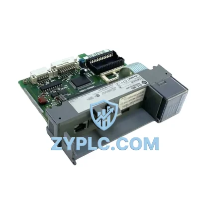
Allen-Bradley 1336F-MCB-SP2L 164989 System-Ready Control Board for 1336 Plus Architecture
The Allen-Bradley 1336F-MCB-SP2L 164989 is a factory-original main control board engineered for seamless integration within the 1336 Plus AC drive platform. Rather than functioning as a standalone replacement component, this board occupies a critical position in the layered automation architecture — bridging the control layer, power conversion layer, and communication network to deliver consistent, reliable drive performance across demanding industrial environments. Whether deployed in a new panel build or as a precision replacement in an existing system, the 1336F-MCB-SP2L 164989 restores full drive intelligence while preserving the system-level coherence that modern automation engineers depend on.
In a complete 1336 Plus drive system, the main control board serves as the central processing element that interprets command signals from the supervisory controller, executes velocity and torque regulation algorithms, manages I/O interface logic, and coordinates communication with upstream PLCs and HMI devices. Its role is inseparable from the broader control hierarchy — and its correct specification is essential to maintaining system uptime, diagnostic accuracy, and long-term maintainability.
Architecture Specification Table
| Parameter |
Specification |
| Part Number |
1336F-MCB-SP2L 164989 |
| Brand |
Allen-Bradley (Rockwell Automation) |
| Series |
1336 Plus AC Drive |
| Component Role |
Main Control Board (MCB) |
| System Layer |
Drive Control Layer |
| Compatible Drive Frame |
1336 Plus Series (Frame B/C, voltage-class dependent) |
| Communication Capability |
Compatible with 1336-GM-xx adapter modules (DH+, DeviceNet, ControlNet, Remote I/O) |
| Analog I/O |
Analog reference input, analog output for speed/torque feedback |
| Digital I/O |
Programmable digital inputs/outputs for run, fault, direction, and speed select |
| Parameter Storage |
Non-volatile onboard EEPROM for drive parameter retention |
| Operating Temperature |
0°C to 50°C (ambient, drive enclosure dependent) |
| Mounting |
Internal drive chassis, direct board replacement |
| Electrical Interface |
Multi-pin ribbon and discrete connector interface to power board and gate driver |
| Warranty |
12-Month Warranty from ZYPLC |
| Condition |
New / Surplus New / Refurbished (specify at order) |
| Origin |
USA (Rockwell Automation OEM) |
Coordinated Control System Design
The 1336F-MCB-SP2L 164989 does not operate in isolation — its value is realized through tight coordination with every layer of the drive system and the broader plant automation architecture. Understanding these interdependencies is essential for engineers specifying replacements or designing new drive panels.
At the power conversion layer, the control board interfaces directly with the 1336 Plus power board and gate driver assembly, translating digital control commands into precise IGBT switching signals. Any mismatch between the control board firmware revision and the power board hardware generation can introduce fault codes or unstable modulation — making exact part number verification critical. The 1336-PB-SP2 power board and associated gate driver modules must be confirmed compatible before installation.
At the network and communication layer, the 1336 Plus platform supports a range of communication adapter modules mounted to the drive’s option slot. The 1336-GM-1 (Remote I/O adapter), 1336-GM-2 (DH+ adapter), and 1336-GM-6 (DeviceNet adapter) all rely on the main control board’s internal communication bus to exchange data with the supervisory PLC. In ControlLogix or PLC-5 based architectures, the 1336F-MCB-SP2L 164989 enables the drive to appear as a fully addressable node on the plant network, supporting parameter read/write, fault diagnostics, and remote speed reference — all without additional signal conditioning hardware.
At the supervisory control layer, the 1336 Plus drive is typically commanded by a 1756-L7x ControlLogix or legacy 1785-Lx PLC-5 processor. The control board’s I/O logic interprets hardwired start/stop, speed reference, and direction signals from the PLC output modules, while simultaneously reporting drive status back through the communication adapter. This bidirectional data flow is what enables closed-loop process control — for example, maintaining constant conveyor speed despite load variation in a packaging line, or regulating pump flow in a water treatment facility.
At the human-machine interface layer, operators interact with the 1336 Plus drive through a 1336-MOD-L2 or compatible LCD operator interface panel, which connects directly to the control board’s HIM port. Drive parameters, fault history, and real-time operating data are all managed through this interface. When the control board is replaced, parameter re-entry or upload from a 1336-MODL-L2E remote HIM or DriveExplorer software session is required to restore the drive’s application-specific configuration.
At the power supply layer, the 1336 Plus drive’s internal SMPS provides regulated DC rails to the control board. Engineers should verify that the 1336-PS-SP1 or equivalent internal power supply is functioning correctly before replacing the control board, as a degraded supply rail is a common root cause of control board failure. Similarly, the 1336-BRF-SP1 brake resistor assembly and associated dynamic braking circuitry must be inspected to ensure no fault condition has propagated from the braking circuit to the control electronics.
For systems requiring redundancy or hot-standby capability, the 1336 Plus platform can be integrated into a dual-drive redundant architecture using external bypass contactors and a 1336-BRD-SP1 bypass/isolation module. In these configurations, the control board’s digital I/O is used to signal drive health status to the redundancy controller, enabling automatic switchover without process interruption. Maintaining a spare 1336F-MCB-SP2L 164989 in the plant storeroom is a recognized best practice for facilities operating continuous processes where drive downtime is not acceptable.
Application in Layered Automation Systems
The 1336F-MCB-SP2L 164989 finds application across a broad spectrum of industrial sectors where the 1336 Plus drive platform has been deployed as a standard motion control solution.
In manufacturing and assembly environments, 1336 Plus drives control conveyor systems, rotary indexers, and material handling equipment. The control board’s programmable I/O enables integration with safety relay modules and machine safety controllers, supporting SIL-rated stop functions without requiring a separate safety drive.
In power generation and utilities, 1336 Plus drives are used for boiler feed pump control, cooling tower fan regulation, and auxiliary motor management. The control board’s analog output provides a 4–20 mA speed feedback signal to the DCS, enabling the drive to participate in plant-wide process control loops managed by a Honeywell or Emerson distributed control system.
In petrochemical and refining facilities, the drive’s ability to operate in hazardous-area-adjacent control rooms — with the motor located in the classified zone — makes the 1336 Plus a preferred solution for pump and compressor control. The control board’s fault logging capability supports the detailed maintenance records required by process safety management (PSM) regulations.
In water and wastewater treatment plants, 1336 Plus drives regulate submersible pump motors, aeration blowers, and sludge dewatering equipment. The control board’s PID reference capability allows the drive to accept a 4–20 mA level sensor signal and autonomously regulate pump speed to maintain constant tank level — reducing PLC scan load and improving response time.
In mining and mineral processing, the 1336 Plus platform is used for crusher feed conveyors, ball mill drives, and flotation cell agitators. The control board’s robust fault detection — including overcurrent, overvoltage, ground fault, and thermal overload — provides the early warning capability needed to prevent catastrophic motor failures in remote or difficult-to-access installations.
In packaging and food processing lines, the 1336 Plus drive’s precise speed regulation ensures consistent product throughput and minimizes waste. The control board’s multi-speed preset capability allows the line controller to select between indexed speed references for different product formats without requiring analog signal rewiring.
Architecture Engineering FAQ
Q1: Is the 1336F-MCB-SP2L 164989 compatible with all 1336 Plus drive frame sizes and voltage classes?
The 1336F-MCB-SP2L is designed for specific frame and voltage configurations within the 1336 Plus family. Compatibility depends on the drive’s catalog number suffix, firmware revision, and power board generation. Before ordering, engineers should cross-reference the existing drive’s nameplate data and the original control board part number to confirm a direct replacement. ZYPLC’s technical team can assist with compatibility verification using the drive’s full catalog number and serial number prefix.
Q2: What steps are required to restore drive operation after replacing the control board?
After physical installation, the replacement control board will typically contain factory default parameters. The drive must be recommissioned by re-entering all application-specific parameters — including motor nameplate data, speed limits, acceleration/deceleration ramps, I/O assignments, and communication node address. If a parameter backup was previously saved using DriveExplorer or a 1336-MODL-L2E remote HIM, the restore process can be completed in minutes. If no backup exists, parameters must be re-entered manually from the original commissioning documentation. A full no-load and loaded test run should be performed before returning the drive to production service.
Q3: What does the 12-Month Warranty from ZYPLC cover, and how is a warranty claim processed?
ZYPLC’s 12-Month Warranty covers manufacturing defects and functional failures under normal operating conditions for the 1336F-MCB-SP2L 164989 from the date of shipment. The warranty does not cover damage resulting from incorrect installation, overvoltage events, contamination, or unauthorized modification. To initiate a warranty claim, contact ZYPLC at plc.sales@zyplc.com or +86 19859288691 with the original order number, a description of the fault symptom, and any available fault code data from the drive. ZYPLC will arrange inspection and, where applicable, replacement or repair at no additional cost within the warranty period.
© 2026 ZYPLC. All rights reserved.
Original Source: https://zyplc.com
Contact: +86 19859288691 | plc.sales@zyplc.com