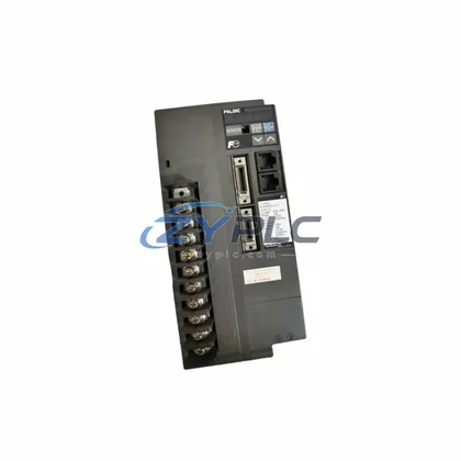
Allen-Bradley 2198-D012-ERS3 EtherNet/IP Servo Drive | Kinetix 5500: availability, compatibility, and sourcing support
The Allen-Bradley 2198-D012-ERS3 is a dual-axis EtherNet/IP servo drive from the Kinetix 5500 series, engineered to serve as a high-performance industrial network interface within modern smart factory architectures. Designed for seamless integration across field devices, PLC controllers, remote I/O modules, HMI panels, SCADA platforms, variable frequency drives, precision sensors, and upper-level MES systems, the 2198-D012-ERS3 delivers deterministic motion control and real-time data transparency across the entire automation data chain.
At its core, the 2198-D012-ERS3 leverages the EtherNet/IP protocol with CIP Motion to establish a unified communication backbone between servo axes and the broader control network. Signal acquisition begins at the encoder and feedback device level, where high-resolution position and velocity data are captured and transmitted over the standard Ethernet infrastructure — eliminating the need for proprietary motion buses and reducing wiring complexity on the plant floor. This architecture enables the drive to function not merely as a motion actuator, but as an intelligent network node contributing live process data to the connected automation ecosystem.
Compatibility & Integration Notes
| Parameter |
Specification |
| Communication Protocol |
EtherNet/IP, CIP Motion |
| Interface Type |
Dual RJ45 Ethernet Ports (embedded switch) |
| Axes Supported |
Dual-Axis |
| Network Compatibility |
Standard IEEE 802.3 Ethernet, Linear / Ring / Star Topology |
| System Application |
Kinetix 5500, Studio 5000 Logix Designer, ControlLogix, CompactLogix |
| SCADA / HMI Integration |
FactoryTalk View, RSLinx Classic, FactoryTalk Historian |
| Real-Time Data |
Position, Velocity, Torque, Fault Status via CIP Motion attributes |
| Remote Diagnostics |
Supported via EtherNet/IP explicit messaging and Studio 5000 |
| Warranty |
Warranty and support terms confirmed before quote |
| Origin |
United States (Allen-Bradley / Rockwell Automation) |
Connected Automation Data Flow
In a typical Kinetix 5500 deployment, the 2198-D012-ERS3 sits at the intersection of motion execution and network intelligence. The data flow originates at the servo motor and feedback device — commonly a 2198-H040-ERS3 single-axis drive or a paired axis within the same 2198-D012-ERS3 chassis — where encoder pulses and torque feedback are digitized and passed upstream via CIP Motion over EtherNet/IP.
The drive connects directly to a ControlLogix or CompactLogix PLC — such as the 1756-L85E or 1769-L36ERM — which executes the motion program within Studio 5000 Logix Designer. The PLC acts as the CIP Motion coordinator, issuing position and velocity commands to the 2198-D012-ERS3 at deterministic scan rates, while simultaneously collecting drive status, fault codes, and axis diagnostics for upstream reporting.
Remote I/O expansion modules, such as the POINT I/O 1734-AENT or ArmorBlock 1732E series, feed digital and analog signals from field sensors — proximity switches, photoelectric sensors, pressure transducers — into the same EtherNet/IP network. These signals are processed by the PLC and correlated with servo axis data to enable coordinated multi-axis motion sequences and condition-based interlocking.
At the HMI layer, a PanelView Plus 7 or FactoryTalk View SE station visualizes real-time axis position, drive temperature, bus voltage, and fault history sourced directly from the 2198-D012-ERS3 via the EtherNet/IP data path. Operators can acknowledge faults, initiate homing sequences, and monitor cycle times without leaving the HMI interface. For plants running FactoryTalk Historian, drive performance data is time-stamped and archived for trend analysis, OEE calculation, and predictive maintenance workflows.
Variable frequency drives such as the PowerFlex 525 or PowerFlex 755 may share the same EtherNet/IP segment, enabling coordinated speed and torque control across servo and induction motor axes within a single SCADA-visible network. The embedded dual-port Ethernet switch in the 2198-D012-ERS3 supports linear and Device Level Ring (DLR) topologies, providing network redundancy and minimizing downtime in high-availability production lines.
Edge gateway devices — including the Stratix 5700 managed switch or a Cisco IE series industrial switch — segment and prioritize EtherNet/IP traffic, ensuring that CIP Motion isochronous real-time (IRT) packets receive deterministic bandwidth allocation alongside standard TCP/IP traffic from SCADA and MES systems. This layered network architecture positions the 2198-D012-ERS3 as a fully integrated node within the Purdue Model reference architecture, bridging Level 1 motion control with Level 2 supervisory systems.
Solving Data Isolation in Industrial Sites
Many industrial facilities operate with fragmented automation islands — servo drives running on proprietary motion buses, PLCs communicating over legacy serial protocols, and HMI systems with no live connection to drive-level diagnostics. The result is data isolation: maintenance teams cannot remotely diagnose a tripping drive, production managers cannot correlate axis faults with throughput losses, and engineering teams cannot validate motion tuning without physical access to the control panel.
The Allen-Bradley 2198-D012-ERS3 directly addresses these challenges by standardizing on EtherNet/IP and CIP Motion — open, widely adopted industrial protocols that integrate natively with Rockwell Automation’s entire control ecosystem. By replacing proprietary motion buses with standard Ethernet infrastructure, the 2198-D012-ERS3 enables plant-wide data transparency: every axis position, drive fault, bus voltage reading, and thermal warning is accessible from any EtherNet/IP node on the network, including remote SCADA workstations and cloud-connected edge gateways.
Protocol unification eliminates the need for standalone protocol converters or gateway devices between the servo layer and the PLC layer, reducing network latency and simplifying troubleshooting. When a drive fault occurs, the ControlLogix PLC captures the fault code, timestamps it, and forwards it to FactoryTalk Historian and the HMI alarm server simultaneously — enabling rapid root-cause analysis without manual log retrieval.
For production line transparency, the 2198-D012-ERS3 supports explicit messaging, allowing SCADA systems to poll drive parameters — including load percentage, regenerative energy, and encoder health — on demand. This data feeds into OEE dashboards and predictive maintenance algorithms, enabling condition-based maintenance scheduling rather than fixed-interval servicing. System expansion is equally straightforward: additional Kinetix 5500 axes can be added to the same EtherNet/IP segment without reconfiguring the network topology, supporting phased capacity increases as production demands grow.
Industrial Connectivity FAQ
Q1: What is the communication latency of the 2198-D012-ERS3 on an EtherNet/IP network?
The 2198-D012-ERS3 supports CIP Motion isochronous real-time communication with configurable coarse update periods as low as 1 ms, enabling deterministic servo synchronization across multiple axes on a standard EtherNet/IP network. Actual latency depends on network topology, switch configuration, and the number of nodes on the segment.
Q2: Is the 2198-D012-ERS3 compatible with non-Rockwell SCADA and HMI systems?
Yes. Because the drive communicates over standard EtherNet/IP with CIP object model support, it can be accessed by any SCADA or HMI platform with an EtherNet/IP driver — including Wonderware, Ignition by Inductive Automation, and Siemens WinCC via third-party EtherNet/IP OPC-UA bridges. Native integration is optimized for FactoryTalk View and Studio 5000.
Q3: How does the embedded dual-port Ethernet switch support network stability?
The integrated dual-port switch enables Device Level Ring (DLR) topology, which provides automatic network recovery in under 3 ms when a cable or node failure is detected. This eliminates single points of failure on the EtherNet/IP segment and ensures continuous motion control without PLC intervention during network fault events.
Q4: What does the warranty and support terms confirmed before quote cover, and has the unit been tested before shipment?
Every 2198-D012-ERS3 unit supplied by ZYPLC undergoes pre-shipment functional testing to verify communication initialization, axis configuration, and fault response behavior. The warranty and support terms confirmed before quote covers manufacturing defects and component failures under normal operating conditions. Units are shipped from verified inventory with full traceability documentation available upon request.