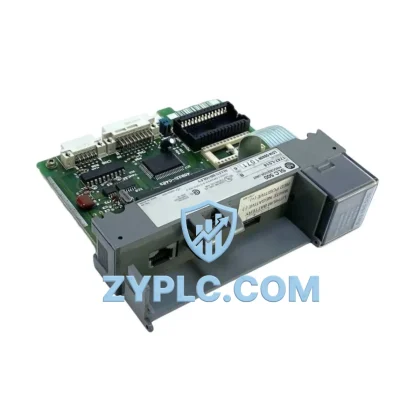
Allen-Bradley D31705-1 A26491-A System-Ready Drive Control for 1336 PLUS Architecture
The Allen-Bradley D31705-1 A26491-A is a purpose-engineered drive control board designed to operate as a core functional layer within the 1336 PLUS AC drive platform. Rather than functioning as a standalone replacement component, this board is best understood within the broader context of a layered industrial control system — where the drive control layer must maintain seamless coordination with the CPU layer, I/O layer, power supply layer, communications network, HMI interface, and field execution devices. In distributed automation environments spanning manufacturing, power generation, petrochemical processing, water treatment, mining, metallurgy, and packaging lines, the integrity of the drive control board directly determines system uptime, signal fidelity, and long-term operational reliability.
The D31705-1 A26491-A board governs the core switching logic, gate drive signals, and feedback processing within the 1336 PLUS drive chassis. Its role in the control architecture is to translate command signals from the upper control layer — typically a ControlLogix or SLC 500 series PLC — into precise PWM output sequences that regulate motor torque, speed, and direction. When this board operates correctly, the entire drive system maintains synchronization with the process control loop, ensuring that field actuators respond predictably to setpoint changes issued from the supervisory layer.
Architecture Specification Table
| Parameter |
Specification |
| Part Number |
D31705-1 A26491-A |
| Brand |
Allen-Bradley |
| Compatible Platform |
1336 PLUS AC Drive Series |
| System Role |
Drive Control Board — Gate Drive & Feedback Processing Layer |
| Electrical Interface |
Internal drive backplane; low-voltage logic and gate signal bus |
| Communication Capability |
Compatible with 1336 PLUS drive communication adapter modules (DeviceNet, DH+, Remote I/O) |
| Installation Environment |
Industrial control cabinet; DIN rail or chassis-mount per 1336 PLUS enclosure standard |
| Operating Temperature |
0°C to 50°C (standard industrial enclosure conditions) |
| Humidity |
5% to 95% non-condensing |
| Product Type |
Drive Control Board |
| Origin |
United States |
| Warranty |
12-Month Warranty — covers manufacturing defects and functional failure under normal operating conditions |
Coordinated Control System Design
The D31705-1 A26491-A does not operate in isolation. Its value is realized only when it is correctly integrated within a complete 1336 PLUS drive system and connected to the broader automation architecture. In a typical layered control design, the 1336 PLUS drive chassis houses multiple coordinated boards: the main control board, the power interface board, the gate driver board, and the human interface module. The D31705-1 A26491-A occupies the drive control position within this chassis, receiving logic-level commands and translating them into high-frequency switching signals for the IGBT power stage.
At the CPU layer, a 1756-L71 ControlLogix processor or a 1747-L553 SLC 5/05 processor issues speed and torque references via the backplane or over a DeviceNet network. These references pass through a 1336-GM1 communication adapter or a 1336-BDB DeviceNet adapter mounted on the 1336 PLUS drive, which then delivers the command data to the D31705-1 A26491-A control board for execution. At the I/O layer, a 1756-IB16 digital input module or 1756-IF8 analog input module captures process feedback signals — such as encoder pulses, pressure transducer outputs, or flow meter signals — and routes them back to the PLC for closed-loop control decisions.
Power integrity is maintained by a 1336-PB series power supply board within the drive chassis, which provides regulated DC bus voltage to the control electronics. Upstream, a 1606-XLP power supply or equivalent 24 VDC panel supply ensures stable logic power for the control cabinet. At the HMI layer, a 2711P-T10C21D8S PanelView Plus 7 terminal provides the operator interface, displaying drive status, fault codes, and process variables sourced from the ControlLogix controller. Terminal blocks such as the 1492-W4 series provide the field wiring interface between the drive output signals and the motor starter or contactor circuit.
In redundant drive architectures — common in critical pump stations, compressor control systems, and continuous process lines — a standby 1336 PLUS drive with an identical D31705-1 A26491-A board is maintained in hot-standby or cold-standby configuration. The 1756-RM2 ControlLogix redundancy module coordinates the switchover logic, ensuring that a failed primary drive is replaced by the standby unit within the system’s defined fault tolerance window. Maintaining a verified spare D31705-1 A26491-A board in the site inventory is therefore a standard engineering practice in high-availability automation systems.
Application in Layered Automation Systems
In manufacturing and assembly line automation, the 1336 PLUS drive controlled by the D31705-1 A26491-A board manages conveyor belt speed, robotic axis positioning, and spindle drive control. The drive’s ability to maintain precise speed regulation under variable load conditions is critical to maintaining product quality and throughput consistency across multi-station production lines.
In power generation and electrical utility applications, the 1336 PLUS platform is deployed for auxiliary motor control — cooling fans, feedwater pumps, and fuel handling conveyors. The D31705-1 A26491-A board’s reliable gate drive output ensures that motor starts and stops occur within the defined ramp profiles, preventing mechanical shock and reducing wear on rotating equipment.
In petrochemical and refinery process control, the drive control board supports variable-speed pump and compressor applications where flow rate must be continuously modulated in response to process pressure and temperature signals. Integration with the ControlLogix PLC via DeviceNet or Remote I/O allows the drive to participate in the plant-wide DCS architecture, receiving setpoints from the supervisory control layer and reporting status back to the SCADA system.
In water and wastewater treatment facilities, the 1336 PLUS drive manages submersible pump motors, aeration blowers, and sludge handling equipment. The D31705-1 A26491-A board’s stable operation under high-humidity, variable-load conditions makes it well-suited for the demanding electrical environment of water treatment infrastructure.
In mining, metallurgy, and heavy industry, the drive control board supports high-inertia load applications including conveyor drives, crusher motors, and mill drives. The ability to maintain controlled acceleration and deceleration profiles under heavy mechanical loads is a key system requirement, and the D31705-1 A26491-A board’s gate drive precision directly supports this capability.
Architecture Engineering FAQ
Q1: Is the D31705-1 A26491-A compatible with all 1336 PLUS drive frame sizes, and what system verification steps are required before installation?
The D31705-1 A26491-A is designed for specific frame configurations within the 1336 PLUS series. Before installation, engineers should verify the drive catalog number, firmware revision, and power rating to confirm board compatibility. The drive should be de-energized and the DC bus fully discharged before board removal or installation. After replacement, the drive parameters stored in the 1336 PLUS parameter memory should be verified against the site configuration record to ensure that speed references, ramp times, and fault response settings are correctly restored.
Q2: How does this board integrate with ControlLogix or SLC 500 architectures, and what communication adapters are required for contextual integration?
Contextual integration of the D31705-1 A26491-A within a ControlLogix or SLC 500 architecture is achieved through the 1336 PLUS communication adapter slot. A 1336-GM1 (Remote I/O), 1336-BDB (DeviceNet), or 1336-GD2 (DH+) adapter module connects the drive to the plant network, allowing the PLC to issue speed commands, read drive status, and respond to fault conditions in real time. The D31705-1 A26491-A board processes these commands internally and generates the corresponding gate drive signals, maintaining full contextual integration between the drive layer and the supervisory control architecture.
Q3: What does the 12-Month Warranty cover, and how should spare board inventory be managed for long-term maintenance planning?
The 12-Month Warranty covers manufacturing defects and functional failures occurring under normal operating conditions within twelve months of the shipment date. It does not cover damage resulting from incorrect installation, overvoltage events, or operation outside the specified environmental parameters. For long-term maintenance planning, it is recommended to maintain at least one verified spare D31705-1 A26491-A board per site operating multiple 1336 PLUS drives. Spare boards should be stored in anti-static packaging in a climate-controlled environment and periodically inspected to confirm physical integrity. Coordinating spare parts procurement with the 12-Month Warranty cycle ensures that replacement boards are always within their warranty coverage period when deployed.
© 2026 ZYPLC. All rights reserved.
Original Source: https://zyplc.com
Contact: +86 19859288691 | plc.sales@zyplc.com