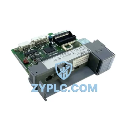
Applied Materials TXZ-0100-01629 Energy-Saving MFC PCB GF125C: Precision Flow Control for Optimized CVD Automation
The Applied Materials TXZ-0100-01629 GF125C MFC PCB Assembly (full SKU: TXZ 0100-01629 GF125C-102895 GF125CXXC N2 280SCCM GF125C-102896 0190-32365 GF125CXXC) is a high-precision mass flow controller PCB module engineered for semiconductor fabrication environments where energy efficiency, process repeatability, and uptime are non-negotiable. Designed for integration into Chemical Vapor Deposition (CVD) and plasma etch systems, this module delivers stable, low-drift gas flow regulation at 280 SCCM for N2 and compatible process gases — directly reducing overconsumption of process gases and the energy overhead associated with flow instability.
In modern semiconductor fabs and advanced industrial automation lines, uncontrolled or imprecise gas flow translates directly into wasted energy, yield loss, and unplanned downtime. The TXZ-0100-01629 addresses this at the hardware level: its onboard signal conditioning and closed-loop feedback circuitry maintain setpoint accuracy across extended production cycles, reducing the need for frequent recalibration and minimizing process gas waste — a key lever in fab-level energy cost reduction.
Efficiency Performance Table
| Parameter |
Specification / Value |
| Full SKU |
TXZ 0100-01629 GF125C-102895 GF125CXXC N2 280SCCM GF125C-102896 0190-32365 GF125CXXC |
| Brand |
Applied Materials |
| Series |
GF125C |
| Module Type |
Mass Flow Controller PCB Assembly |
| Flow Range |
280 SCCM (N2 equivalent) |
| Gas Compatibility |
N2 and compatible inert/process gases |
| Application Environment |
CVD, Plasma Etch, Semiconductor Fab, Industrial Automation |
| Control Architecture |
Closed-loop analog/digital feedback PCB |
| Energy Optimization Value |
Reduces process gas overconsumption; minimizes recalibration downtime |
| Compatible Systems |
Applied Materials CVD/Etch platforms, GF125C-series MFC housings |
| Origin |
USA |
| Inventory Status |
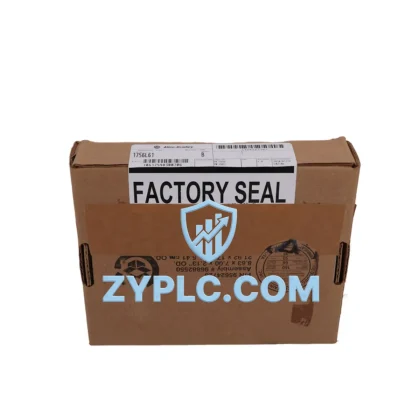
In Stock — Ships Fast |
| Warranty |
12-Month Warranty |
Energy-Aware Automation Architecture
The TXZ-0100-01629 GF125C PCB module does not operate in isolation — it is a critical node within a broader energy-aware automation architecture. In a typical CVD process cell, the MFC PCB interfaces directly with the chamber’s gas delivery manifold and receives setpoint commands from the process controller, often an Applied Materials system controller or a compatible PLC platform such as the Allen-Bradley ControlLogix L73 or Siemens S7-1500 series PLC. These controllers issue flow commands via analog 0–5V or digital fieldbus signals, and the GF125C PCB translates those commands into precise valve actuation — ensuring that gas consumption tracks process demand rather than running at fixed, wasteful rates.
Upstream of the MFC, process gas pressure is regulated by inlet pressure controllers and monitored by capacitance manometers such as the MKS Baratron 627D or equivalent transducers. Accurate upstream pressure data fed back to the control loop allows the TXZ-0100-01629 to compensate for supply fluctuations in real time, preventing the flow overshoot that wastes gas and energy. Downstream, the MFC output feeds into the chamber via a heated gas line, where temperature uniformity — managed by zone controllers like the Watlow EZ-ZONE PM — further reduces energy loss from condensation or thermal gradient compensation.
At the drive and power layer, the fab’s energy profile is shaped by variable frequency drives (VFDs) such as the Yaskawa GA800 or ABB ACS880 controlling vacuum pump motors and exhaust blowers. When the TXZ-0100-01629 delivers stable, on-setpoint flow, these downstream pumping systems operate at their designed load points rather than hunting under variable gas loads — directly improving motor efficiency and reducing kWh consumption per wafer pass. Power monitoring modules such as the Schneider Electric PowerLogic ION7650 or Siemens SENTRON PAC3200 can be deployed at the process tool level to quantify these energy savings in real time, providing the data foundation for ISO 50001 energy management reporting.
For I/O integration, the GF125C PCB assembly is compatible with standard analog I/O modules — including the Applied Materials 0190-32365 referenced in the SKU cross-reference — which handle signal routing between the MFC and the tool’s main I/O chassis. In modernized fab environments, this I/O layer may be extended via EtherNet/IP or PROFIBUS DP communication adapters, enabling the MFC’s real-time flow data to be aggregated into the fab’s Manufacturing Execution System (MES) or SCADA platform for energy analytics and predictive maintenance scheduling.
Power Optimization in Real Production Lines
In a high-volume CVD production line running 24/7, even a 2–3% improvement in gas flow accuracy translates into measurable reductions in process gas consumption — one of the largest variable operating costs in semiconductor manufacturing. The TXZ-0100-01629 GF125C PCB module contributes to this optimization through several mechanisms:
Reduced Idle Gas Flow: The closed-loop PCB architecture enables fast setpoint response, allowing the process controller to ramp gas flows down during idle and standby states without risking flow instability at recipe start. This reduces the volume of process gas consumed during non-productive tool states — a common source of hidden energy waste in fabs running multiple recipe steps per day.
Minimized Recalibration Downtime: MFC drift is a leading cause of unplanned maintenance windows in CVD tools. The GF125C series PCB is designed for long-term stability, reducing the frequency of in-situ calibration checks and the associated tool downtime. Fewer maintenance interruptions mean higher equipment utilization rates (OEE) and lower energy cost per productive wafer hour.
Predictive Maintenance Integration: When integrated with a condition monitoring system — such as a SCADA platform collecting analog output signals from the MFC — subtle changes in the TXZ-0100-01629’s response curve can be detected before they cause process excursions. This predictive maintenance approach prevents the energy-intensive recovery cycles (purge sequences, pump-down cycles, re-qualification runs) that follow an unplanned MFC failure.
Optimized Line Takt: Stable, repeatable gas flow directly supports consistent process cycle times. When flow variability is eliminated as a source of recipe deviation, the process controller can execute tighter takt windows — improving throughput per unit of energy consumed and reducing the per-wafer energy cost across the production line.
All units are tested prior to shipment under simulated operating conditions, with flow accuracy verified against calibrated reference standards. Each TXZ-0100-01629 GF125C PCB module ships with full documentation and is covered by a 12-month warranty from the date of delivery, ensuring supply continuity and minimizing the financial risk of integration into critical production equipment.
Energy Optimization FAQ
Q1: How does the TXZ-0100-01629 GF125C MFC PCB contribute to energy savings in a CVD process tool?
By maintaining precise closed-loop flow control at 280 SCCM, the module eliminates flow overshoot and undershoot that force the process system to compensate — wasting process gas and increasing pump load. Stable flow means the vacuum and exhaust systems operate at their designed efficiency points, reducing overall tool energy consumption per process cycle.
Q2: Is the TXZ-0100-01629 compatible with my existing Applied Materials CVD or etch system?
This PCB assembly is designed for GF125C-series MFC housings used in Applied Materials CVD and plasma etch platforms. The cross-reference SKUs (GF125C-102895, GF125C-102896, 0190-32365) cover the most common GF125CXXC configurations. If you are unsure of compatibility, please contact us with your tool model and current MFC part number for verification before ordering.
Q3: What is the recommended replacement interval, and how do I know when the PCB needs replacement?
Typical MFC PCB service life in a production CVD environment is 3–5 years under normal operating conditions, but this varies with process chemistry and duty cycle. Indicators that replacement may be needed include increasing flow deviation from setpoint, erratic valve response, or failure to hold calibration between PM cycles. Proactive replacement during scheduled preventive maintenance windows avoids unplanned downtime and the associated energy cost of recovery sequences.
Q4: What does the 12-month warranty cover, and what is the testing process before shipment?
Every TXZ-0100-01629 GF125C PCB module undergoes functional testing prior to shipment, including flow response verification and signal integrity checks. The 12-month warranty covers defects in materials and workmanship under normal operating conditions. Units that fail within the warranty period are repaired or replaced at no charge. For time-critical production environments, expedited replacement options are available — contact our sales team to discuss inventory reservation and priority fulfillment arrangements.
© 2026 ZYPLC. All rights reserved.
Original Source: https://zyplc.com
Contact: +86 19859288691 | plc.sales@zyplc.com