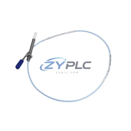
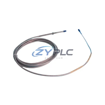
Bently Nevada 190501-09-99-00 Velocity Sensor for Velomitor CT Control System
The Bently Nevada 190501-09-99-00 Velomitor CT Velocity Sensor is engineered not merely as a standalone measurement device, but as a precision-integrated component within a layered industrial control system architecture. In modern rotating machinery protection and condition monitoring environments, every sensor, module, and communication node must function as part of a coherent, redundant, and scalable system. The 190501-09-99-00 fulfills this role by delivering high-fidelity velocity signal output that feeds directly into the Bently Nevada 3500 Series machinery protection system, enabling real-time vibration analysis, alarm management, and automated shutdown logic across the full control hierarchy.
Understanding the 190501-09-99-00 requires viewing it within the broader context of the control architecture it supports. From the field instrument layer through the I/O conditioning layer, the communication backbone, the supervisory control layer, and ultimately the human-machine interface, this sensor contributes to system-wide consistency, diagnostic accuracy, and long-term operational reliability. Its compact Velomitor CT design allows direct installation on bearing housings, gearboxes, compressor casings, and pump structures where traditional proximity probes cannot be applied, extending the monitoring reach of the overall system without requiring additional infrastructure investment.
Product Specification Table
| Parameter |
Specification |
| System Role |
Field-Level Velocity Transducer — Machinery Protection Layer |
| Model / SKU |
190501-09-99-00 |
| Series |
Velomitor CT (Compact Top-Exit) |
| Brand |
Bently Nevada |
| Measurement Type |
Absolute Casing Velocity (mm/s or in/s) |
| Frequency Range |
10 Hz – 1,000 Hz (±3 dB) |
| Sensitivity |
100 mV/in/s (4 mV/mm/s) |
| Output Signal |
Analog Voltage, compatible with 3500/42M and 3500/45 monitor modules |
| Supply Voltage |
18–30 VDC (loop-powered via monitor) |
| Operating Temperature |
-40°C to +121°C |
| Ingress Protection |
IP67 (dust-tight, water-immersion rated) |
| Connector / Cable Exit |
Top-exit, integral cable, MIL-C-5015 compatible |
| Communication Compatibility |
Analog signal to 3500 rack; integrates with System 1 software via rack gateway |
| Installation Environment |
Rotating machinery bearing housings, gearboxes, compressor casings, pump structures |
| Warranty |
Warranty and support terms confirmed before quote — Tested, inspected, and certified prior to shipment |
System Compatibility Notes
The 190501-09-99-00 Velomitor CT sensor achieves its full value when deployed within a coordinated Bently Nevada 3500 Series rack-based protection system. In a typical turbine or compressor protection architecture, the sensor mounts at the bearing housing and transmits a conditioned analog velocity signal to the Bently Nevada 3500/42M Velocity Monitor or 3500/45 Position Monitor installed in the 3500 rack. The rack itself is powered by a redundant 3500/15 Power Supply module, ensuring that no single power failure interrupts the protection chain.
Within the same rack, a 3500/22M Transient Data Interface (TDI) module captures high-resolution waveform data from the velocity channel, enabling engineers to perform spectral analysis and identify developing faults such as unbalance, misalignment, looseness, or bearing defects. The 3500/32 4-Channel Relay Module processes alarm and danger setpoints derived from the velocity signal and triggers automated shutdown sequences or annunciator outputs when thresholds are exceeded, protecting critical assets from catastrophic failure.
At the network and communication layer, the 3500/92 Communication Gateway Module bridges the rack’s internal Bently Nevada protocol to Modbus TCP, PROFIBUS DP, or OPC-UA, allowing the velocity data from the 190501-09-99-00 to be consumed by the plant DCS — such as a Honeywell Experion PKS or Emerson DeltaV — without signal conversion losses. This system integration ensures that the velocity measurement is not isolated within the machinery protection system but is fully visible to the supervisory control and data acquisition (SCADA) layer, enabling cross-system correlation with process variables such as flow, pressure, and temperature.
For human-machine interface visibility, the velocity trend data from the 190501-09-99-00 is displayed on Bently Nevada System 1 Evolution software, which provides real-time waveform plots, trend history, and alarm management dashboards accessible to both field engineers and remote operations centers. In redundant architectures, a secondary 3500/20 Rack Interface Module maintains communication continuity even during primary module maintenance, ensuring that the velocity monitoring channel remains active throughout planned and unplanned maintenance windows.
Terminal blocks and field wiring for the 190501-09-99-00 are typically routed through Bently Nevada 3500/05 System Rack backplane connectors, maintaining signal integrity across long cable runs in electrically noisy industrial environments. The sensor’s high common-mode rejection and shielded cable construction minimize interference from variable frequency drives (VFDs), high-voltage switchgear, and adjacent instrumentation — a critical requirement in petrochemical, power generation, and mining applications where electromagnetic compatibility directly affects measurement reliability.
Industrial Application Notes
In power generation facilities — including gas turbines, steam turbines, and hydro generators — the 190501-09-99-00 is deployed on non-drive-end bearing housings where eddy-current proximity probes cannot be installed due to shaft material constraints. The sensor’s wide frequency response captures both low-frequency rotor imbalance signatures and high-frequency gear mesh frequencies, providing a comprehensive vibration profile that supports both protection and predictive maintenance programs.
In petrochemical and refinery environments, the Velomitor CT’s IP67 rating and high-temperature tolerance make it suitable for installation on process compressors, boiler feed pumps, and cooling tower fans operating in humid, corrosive, or high-ambient-temperature conditions. The sensor integrates seamlessly into Safety Instrumented System (SIS) architectures by providing a hardwired analog output that can be monitored by both the Bently Nevada protection rack and an independent IEC 61511-compliant safety logic solver, supporting SIL 2 machinery protection loops.
In mining and mineral processing applications, the 190501-09-99-00 monitors SAG mills, ball mills, conveyor drive gearboxes, and crusher bearings — assets where vibration-induced failures result in extended production shutdowns and significant revenue loss. The sensor’s robust mechanical construction withstands the high-shock and high-vibration environments characteristic of these applications, while its analog output remains stable across the full operating temperature range encountered in open-pit and underground mining operations.
For water and wastewater treatment plants, the sensor is applied to large centrifugal pumps, blowers, and dewatering equipment. Its compatibility with the Bently Nevada 3500 rack system allows water utility operators to implement a standardized machinery protection platform across multiple pump stations, reducing spare parts inventory complexity and enabling centralized remote monitoring through a unified System 1 software instance.
In packaging and discrete manufacturing production lines, the 190501-09-99-00 provides continuous vibration monitoring on high-speed rotating equipment such as centrifuges, fans, and gearboxes, enabling condition-based maintenance scheduling that reduces downtime and extends mean time between failures (MTBF) for critical production assets.
Product Compatibility FAQ
Q1: Is the Bently Nevada 190501-09-99-00 compatible with the 3500 Series rack system, and what monitor modules does it interface with?
Yes. The 190501-09-99-00 Velomitor CT outputs a standard analog voltage signal (100 mV/in/s) that is directly compatible with the Bently Nevada 3500/42M Velocity Monitor and 3500/45 Position Monitor modules installed in the 3500/05 rack. No signal conditioning adapter is required. The sensor’s output impedance and frequency response are matched to the input specifications of these monitor modules, ensuring accurate alarm and danger setpoint processing without calibration offset. For systems using the 3500/22M Transient Data Interface, the velocity channel can also be configured for waveform capture and spectral analysis within System 1 Evolution software.
Q2: Can the 190501-09-99-00 be integrated into a redundant machinery protection architecture, and how does it support system availability during maintenance?
The 190501-09-99-00 supports redundant monitoring architectures through dual-channel rack configurations where two sensors are installed at the same measurement point — one connected to the primary monitor channel and one to the backup channel. The 3500 rack’s bypass and inhibit functions allow individual channels to be taken offline for sensor replacement or calibration without triggering spurious shutdowns, maintaining system availability during planned maintenance. The sensor’s integral cable and top-exit connector design simplifies field replacement, reducing mean time to repair (MTTR) and minimizing the duration of any monitoring gap. Warranty terms are confirmed during quotation.
Q3: What is the recommended installation and commissioning procedure for the 190501-09-99-00 in a new control system architecture, and what long-term maintenance considerations apply?
Installation of the 190501-09-99-00 follows Bently Nevada’s standard Velomitor CT mounting guidelines: the sensor should be mounted on a flat, clean surface using the integral mounting stud, with the cable routed away from high-voltage conductors and secured at regular intervals to prevent vibration-induced cable fatigue. During commissioning, the monitor module’s OK setpoint should be verified against the sensor’s output at rest, and the alarm and danger setpoints should be configured based on ISO 10816 or API 670 vibration severity criteria appropriate for the machine type and speed. For long-term maintenance, ZYPLC recommends periodic verification of sensor sensitivity using a portable calibration shaker, inspection of cable integrity at the connector and mounting point, and review of trend data in System 1 Evolution to identify gradual sensitivity drift. Replacement units are available from ZYPLC stock with a Warranty and support terms confirmed before quote, ensuring continuity of the machinery protection architecture without extended lead times.