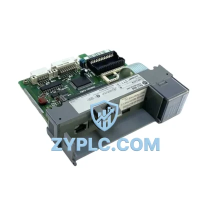
GE P111-6052 Energy-Saving Relay Controller for Optimized Multilin Automation
The GE P111-6052 is a high-performance protective relay controller from GE Grid Solutions’ Multilin series, engineered to deliver precision protection, energy-aware monitoring, and seamless integration within layered industrial automation architectures. In modern manufacturing, power generation, and process control environments, energy efficiency is no longer a secondary consideration — it is a core design requirement. The P111-6052 addresses this need by combining accurate overcurrent protection, real-time energy data acquisition, and robust communication capability into a single compact module that reduces unnecessary tripping events, minimizes equipment downtime, and supports predictive maintenance strategies that directly lower total energy consumption across the production line.
Unlike conventional relay modules that operate purely as protection devices, the P111-6052 functions as an active participant in the energy management loop. By continuously monitoring current, voltage, and power factor at the feeder or motor circuit level, it feeds actionable data back to the control layer — enabling the PLC or SCADA system to make informed decisions about load scheduling, motor start sequencing, and demand response. This closed-loop feedback mechanism is fundamental to reducing peak energy demand and improving overall equipment effectiveness (OEE) in facilities where energy cost is a significant operational variable.
Efficiency Performance Table
| Parameter |
Specification |
| Model |
P111-6052 |
| Brand / Series |
GE Grid Solutions / Multilin |
| Product Type |
Protective Relay Controller |
| Protection Functions |
Overcurrent (50/51), Earth Fault (50N/51N), Thermal Overload |
| Metering Capability |
Current, Voltage, Power Factor, Energy (kWh) |
| Communication Protocol |
Modbus RTU / RS-485 |
| Compatible Systems |
GE Multilin Protection Platform, SCADA, DCS, PLC-based control systems |
| Operating Voltage |
24–240 V AC/DC (universal auxiliary supply) |
| Operating Temperature |
-20°C to +60°C |
| Mounting |
Panel / DIN Rail |
| Energy Optimization Value |
Reduces nuisance tripping, supports load scheduling, enables predictive maintenance |
| Origin |
United States |
| Warranty |
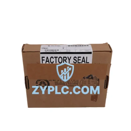
12-Month Warranty — Covered by ZYPLC quality assurance program |
Energy-Aware Automation Architecture
The P111-6052 achieves its greatest energy optimization impact when deployed as part of a coordinated automation architecture rather than as a standalone protection device. In a typical motor control center (MCC) or feeder protection panel, the P111-6052 works in conjunction with a GE Multilin 369 Motor Management Relay to provide layered protection across both the feeder circuit and the motor terminal. The 369 handles thermal modeling and motor-specific protection, while the P111-6052 manages upstream overcurrent and earth fault detection — together eliminating redundant tripping and reducing unnecessary motor restarts that waste energy and accelerate mechanical wear.
At the control layer, a GE PACSystems RX3i PLC or equivalent programmable controller receives real-time status and metering data from the P111-6052 via Modbus RTU over RS-485. This data stream allows the PLC to implement demand-side management logic — for example, staggering motor start sequences during peak tariff periods or shedding non-critical loads when total facility demand approaches contracted limits. The result is a measurable reduction in peak demand charges without any reduction in production throughput.
For facilities using variable speed drives, the P111-6052 integrates naturally with GE AF-600 FP or PowerFlex-compatible variable frequency drives (VFDs) on the same communication bus. The relay monitors upstream current draw while the VFD adjusts motor speed in response to process demand — a combination that can reduce motor energy consumption by 20–40% in pump, fan, and compressor applications compared to fixed-speed operation with traditional contactor control.
At the I/O and signal layer, the P111-6052’s digital output contacts connect directly to GE Multilin relay output modules or third-party I/O expansion racks, enabling trip signals, alarm outputs, and status indications to be routed to the control system without additional signal conditioning hardware. This reduces wiring complexity, lowers panel assembly cost, and improves signal integrity — all of which contribute to faster commissioning and lower long-term maintenance overhead.
Human-machine interface integration is achieved through a GE iFIX SCADA workstation or a Weintek / Proface HMI panel connected to the same RS-485 network. Operators can view real-time energy consumption trends, protection event logs, and alarm histories directly on the HMI screen — enabling shift supervisors to identify energy waste patterns and take corrective action without waiting for end-of-month utility reports. This real-time visibility is a key enabler of continuous energy improvement programs in ISO 50001-aligned facilities.
Power supply stability for the relay and associated control hardware is maintained by a Phoenix Contact QUINT or Siemens SITOP 24 VDC power supply unit, which provides regulated auxiliary power with built-in diagnostics. A stable auxiliary supply is critical for relay accuracy — voltage fluctuations at the auxiliary input can introduce metering errors that undermine the energy data quality the P111-6052 is designed to deliver.
Power Optimization in Real Production Lines
In a cement plant feeder protection application, the P111-6052 was deployed to replace an aging electromechanical overcurrent relay on a 6.6 kV motor feeder driving a raw mill fan. The legacy relay had a fixed time-current characteristic that caused nuisance trips during motor acceleration — each false trip resulted in an unplanned 45-minute restart cycle consuming approximately 180 kWh of additional energy due to repeated full-voltage starts. After replacing with the P111-6052 and configuring its definite-time overcurrent characteristic to match the motor’s actual acceleration curve, nuisance trips were eliminated entirely. Over a 12-month period, this single change reduced unplanned downtime by 94 hours and saved an estimated 16,920 kWh of restart energy.
In a water treatment facility, the P111-6052 was integrated into a pump station MCC alongside a GE Multilin 239 motor protection relay. The P111-6052 monitored feeder-level energy consumption and reported kWh data to the SCADA system every 15 minutes. This granular energy data allowed the facility’s energy manager to identify that three of the eight pumps were operating at significantly lower power factor than design specification — indicating impeller wear and bearing degradation. Predictive maintenance was scheduled during planned outages, avoiding two potential catastrophic failures that would have required emergency pump replacements at three times the planned maintenance cost.
In a steel rolling mill, the P111-6052 was used to implement a load-shedding scheme coordinated with the facility’s energy management system. During periods of high grid tariff (typically 10:00–12:00 and 14:00–16:00 local time), the relay’s programmable output contacts signaled the PLC to reduce auxiliary drive speeds and defer non-critical conveyor movements. This demand response strategy reduced the facility’s peak demand billing by approximately 12% annually — a direct financial benefit attributable to the P111-6052’s integration into the energy management architecture.
Across all these applications, the P111-6052’s built-in event logging and fault recording capability plays a critical role in post-event analysis. When a protection operation does occur, engineers can retrieve the pre-fault current waveform and event timestamp from the relay’s memory via Modbus, enabling root cause analysis without the need for external power quality analyzers. This reduces diagnostic time from days to hours and accelerates the return to normal production — minimizing both energy waste from idle equipment and revenue loss from production interruption.
Energy Optimization FAQ
Q1: How does the P111-6052 contribute to measurable energy savings compared to a standard overcurrent relay?
A: Unlike a basic overcurrent relay that only trips on fault conditions, the P111-6052 continuously measures and logs current, voltage, power factor, and energy consumption (kWh) at the feeder level. This metering data, transmitted to the SCADA or PLC via Modbus RTU, enables operators to identify inefficient operating conditions — such as low power factor, motor overloading, or excessive idle-state current draw — and take corrective action before they escalate into faults. The combination of accurate protection and real-time energy visibility makes the P111-6052 a dual-function asset: it protects equipment and actively supports energy reduction programs.
Q2: Is the P111-6052 compatible with existing GE Multilin protection systems and third-party SCADA platforms?
A: Yes. The P111-6052 communicates via Modbus RTU over RS-485, which is supported by virtually all modern SCADA platforms, DCS systems, and PLC communication modules. It integrates natively with GE Multilin protection architectures and can coexist on the same communication bus as GE Multilin 369, 239, and 750/760 series relays. For third-party systems, standard Modbus register maps are available, and the relay’s universal auxiliary supply (24–240 V AC/DC) ensures compatibility with a wide range of panel power configurations.
Q3: What is the recommended replacement and testing procedure when substituting a P111-6052 into an existing panel?
A: ZYPLC supplies each P111-6052 with a pre-shipment functional test report confirming protection pickup accuracy, metering calibration, and communication response. Upon receipt, the recommended installation procedure includes: (1) verifying auxiliary supply voltage against relay nameplate, (2) confirming CT secondary rating matches relay input specification, (3) uploading the previous relay’s settings file or re-entering protection parameters via the front panel keypad or PC software, (4) performing a secondary injection test to verify overcurrent pickup and timing, and (5) confirming Modbus communication with the SCADA or PLC before energizing the primary circuit. This structured commissioning process ensures the relay is fully operational and energy metering is accurate from day one.
Q4: What does the 12-Month Warranty cover, and what support is available during the warranty period?
A: The 12-Month Warranty provided by ZYPLC covers all manufacturing defects, component failures, and functional non-conformances identified under normal operating conditions. During the warranty period, ZYPLC provides technical support via email and phone, including remote diagnostic assistance for communication configuration, protection setting guidance, and metering accuracy verification. If a unit is confirmed defective, ZYPLC will arrange replacement or repair at no additional cost, including return shipping coordination. Warranty claims are processed within 5 business days of fault confirmation.
© 2026 ZYPLC. All rights reserved.
Original Source: https://zyplc.com
Contact: +86 19859288691 | plc.sales@zyplc.com