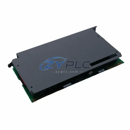
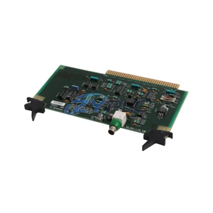
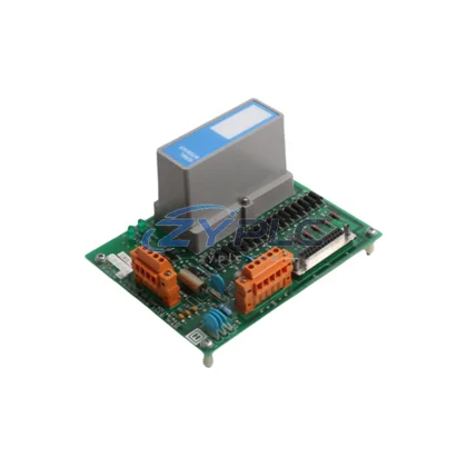
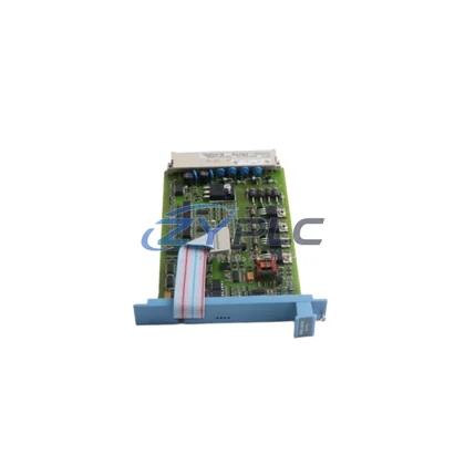
Honeywell MLF-DC04A DC Output Module for MLF Series
The Honeywell MLF-DC04A is a DC output module purpose-built for deployment within the Honeywell MLF Series programmable logic controller platform. In modern industrial automation, no single module operates in isolation — every output card, every I/O rack, and every communication gateway contributes to the integrity of the overall control architecture. The MLF-DC04A is engineered with this systems-first philosophy in mind, delivering reliable digital output switching that integrates seamlessly across control layers, from the CPU backplane to the field device terminals.
Within a layered automation architecture, the MLF-DC04A occupies the I/O layer, translating logic-level commands from the MLF Series CPU into discrete DC switching signals that drive actuators, solenoid valves, motor starters, and relay coils in the field. Its four-channel DC output configuration is optimized for compact panel designs where channel density and signal integrity must be balanced against cabinet space constraints. Each output channel is independently addressable, allowing the CPU — such as the Honeywell MLF-CPU01 or MLF-CPU02 — to execute precise, channel-level control without cross-channel interference.
The module mounts directly onto the MLF Series backplane, sharing the same rack infrastructure as companion modules including the MLF-AI04A analog input module, MLF-DI08A digital input module, and MLF-AO02A analog output module. This shared backplane architecture eliminates the need for external wiring between I/O modules and the CPU, reducing installation complexity and improving signal transmission reliability across the rack. The MLF-DC04A draws its logic power from the rack’s integrated power bus, which is typically supplied by the MLF-PS24 or equivalent MLF Series power supply module, ensuring stable operation even under fluctuating load conditions.
From a network and communication perspective, the MLF-DC04A participates in the broader control system through the CPU’s communication stack. In architectures where the MLF Series controller is networked via Modbus RTU, Modbus TCP/IP, or PROFIBUS DP — facilitated by communication gateway modules such as the MLF-COM01 — the output module’s channel states are fully accessible for remote monitoring, diagnostics, and SCADA integration. This makes the MLF-DC04A a natural fit for distributed control topologies where field I/O must be visible at the supervisory layer without additional hardware overhead.
For system designers working on redundant architectures, the MLF-DC04A supports hot-standby configurations when paired with a redundant CPU module and the appropriate redundancy synchronization hardware. In such setups, output states are mirrored across the primary and standby controllers, ensuring that a CPU failover event does not interrupt the DC output signals driving critical field devices. This redundancy capability is particularly valuable in continuous process industries — such as petrochemical refining, power generation, and water treatment — where unplanned output interruptions carry significant operational and safety consequences.
At the human-machine interface layer, operators interacting with Honeywell HMI panels or SCADA workstations connected to the MLF Series network can monitor the real-time status of each MLF-DC04A output channel, receive diagnostic alerts for output faults, and execute manual override commands during maintenance windows. This end-to-end visibility — from the HMI screen down to the individual output terminal — is a defining characteristic of a well-integrated MLF Series control system.
Product Specification Table
| Parameter |
Specification |
| System Role |
Digital DC Output Module — I/O Layer |
| Compatible Platform |
Honeywell MLF Series PLC |
| Output Channels |
4 x DC Digital Output |
| Output Voltage Range |
12–24 VDC (nominal) |
| Output Current per Channel |
Up to 0.5 A (typical, per channel) |
| Isolation |
Optocoupler isolation per channel |
| Backplane Interface |
MLF Series rack-mount backplane bus |
| Communication Access |
Via CPU (Modbus RTU / Modbus TCP / PROFIBUS DP) |
| Power Supply |
Rack-integrated logic bus (MLF-PS24 compatible) |
| Operating Temperature |
0°C to +55°C |
| Relative Humidity |
5% to 95% non-condensing |
| Mounting |
DIN rail / MLF Series rack slot |
| Protection Class |
IP20 |
| Certifications |
CE, RoHS compliant |
| Warranty |
warranty terms confirmed during quotation — covered against manufacturing defects |
System Compatibility Notes
The MLF-DC04A achieves its full potential when deployed as part of a coordinated MLF Series control system rather than as a standalone component. A typical MLF Series panel configuration begins with the MLF-CPU01 or MLF-CPU02 central processing unit, which manages the scan cycle, executes the control program, and coordinates all I/O module communications across the backplane. The CPU is supported by the MLF-PS24 power supply module, which provides regulated 24 VDC logic power to the entire rack, ensuring that the MLF-DC04A and its companion modules receive stable operating voltage regardless of field load variations.
On the input side, the MLF-DI08A digital input module and MLF-AI04A analog input module feed process signals — discrete switch states, 4–20 mA sensor readings, and thermocouple values — into the CPU’s data table. The CPU processes these inputs against the control program logic and generates output commands that are dispatched to the MLF-DC04A and the MLF-AO02A analog output module. This input-to-output signal flow, mediated entirely through the backplane bus, eliminates the latency and wiring complexity associated with external I/O wiring schemes.
For applications requiring network connectivity, the MLF-COM01 communication gateway module bridges the MLF Series backplane to Ethernet-based SCADA networks or legacy serial fieldbus segments. Terminal modules and marshalling blocks — such as the MLF-TB16 terminal base — provide the physical wiring interface between the MLF-DC04A’s output channels and the field cable trays, simplifying panel wiring and enabling modular replacement of individual I/O modules without disturbing field wiring. In drive-intensive applications, the MLF-DC04A output signals may also serve as enable or direction commands to variable frequency drives (VFDs) or soft starters, completing the execution layer of the control hierarchy.
Industrial Application Notes
The Honeywell MLF-DC04A finds application across a broad spectrum of industrial sectors where reliable DC output switching is a fundamental control requirement. In discrete manufacturing environments — including automotive assembly, electronics production, and packaging lines — the module drives pneumatic solenoid valves, conveyor motor starters, and indicator lamps, providing the precise, repeatable switching performance that high-speed production lines demand.
In the power generation and electrical utility sector, the MLF-DC04A is deployed in substation automation panels and generator control systems, where its optocoupler-isolated outputs provide the electrical separation necessary to protect the PLC backplane from high-energy field circuits. Water and wastewater treatment facilities rely on the module to control pump motor contactors, valve actuators, and chemical dosing systems, with the MLF Series CPU managing complex sequencing logic that responds to level sensors, flow meters, and pressure transmitters connected through companion input modules.
Petrochemical and refinery applications leverage the MLF-DC04A’s compatibility with the MLF Series redundant CPU architecture to maintain continuous output control during planned and unplanned controller maintenance events. Mining and metallurgical operations use the module in conveyor control systems, crusher sequencing panels, and ventilation control cabinets, where the combination of compact form factor, wide operating temperature range, and warranty terms confirmed during quotation support makes the MLF-DC04A a cost-effective choice for remote and harsh-environment installations. In process control applications — including food and beverage, pharmaceutical, and chemical batch processing — the module’s channel-level addressability supports recipe-driven output sequencing that integrates directly with the plant’s DCS or SCADA supervisory layer.
Product Compatibility FAQ
Q1: Is the MLF-DC04A compatible with both MLF-CPU01 and MLF-CPU02 processors, and does it support hot-swap replacement in a running system?
The MLF-DC04A is designed for use across the MLF Series CPU range, including the MLF-CPU01 and MLF-CPU02 processors, sharing the same backplane bus protocol and I/O addressing scheme. Regarding hot-swap capability, this depends on the specific firmware version of the CPU and the rack configuration. In standard single-CPU configurations, module replacement typically requires a controlled shutdown of the affected rack slot. In redundant CPU architectures with the appropriate redundancy module, output continuity can be maintained during module servicing. Always consult the MLF Series hardware installation manual and confirm firmware compatibility before performing live module replacement in safety-critical applications.
Q2: How does the MLF-DC04A integrate with third-party SCADA systems, and what communication protocols are supported for remote output monitoring?
The MLF-DC04A does not communicate independently with external networks — all SCADA and network communication is managed through the MLF Series CPU and its associated communication modules, such as the MLF-COM01 gateway. The CPU exposes the output channel states of the MLF-DC04A through its data table, which is accessible via Modbus RTU over RS-485, Modbus TCP/IP over Ethernet, and PROFIBUS DP, depending on the communication modules installed in the rack. Third-party SCADA systems — including Wonderware, iFIX, and WinCC — can poll these registers using standard driver configurations, enabling real-time output status monitoring, alarm generation, and manual override commands from the supervisory layer without any additional hardware between the PLC and the SCADA server.
Q3: What does the warranty terms confirmed during quotation cover for the MLF-DC04A, and what is the process for warranty replacement if a module fails in service?
The warranty terms confirmed during quotation for the MLF-DC04A covers manufacturing defects, component failures, and workmanship issues that arise under normal operating conditions within the specified environmental and electrical parameters. Physical damage resulting from incorrect installation, overvoltage events, or operation outside the rated temperature and humidity range is not covered under the standard warranty terms. To initiate a warranty replacement, contact ZYPLC at plc.sales@zyplc.com or +86 19859288691 with the module’s serial number, purchase documentation, and a description of the observed fault. ZYPLC maintains RFQ-confirmed sourcing of MLF Series modules to support rapid warranty exchange, minimizing system downtime during the replacement process.