
ZYPLC Blog
KUKA KRC2 and KR C4 Drive Spares: Separate the Servo Fault Before Ordering
A robot that drops drive enable may show an axis alarm, a controller alarm, or a chain of secondary messages created by one power-stage problem. Under production pressure, it is tempting to search the alarm text and order the first KUKA drive module with a similar rating. That shortcut is especially dangerous when KRC2 and […]
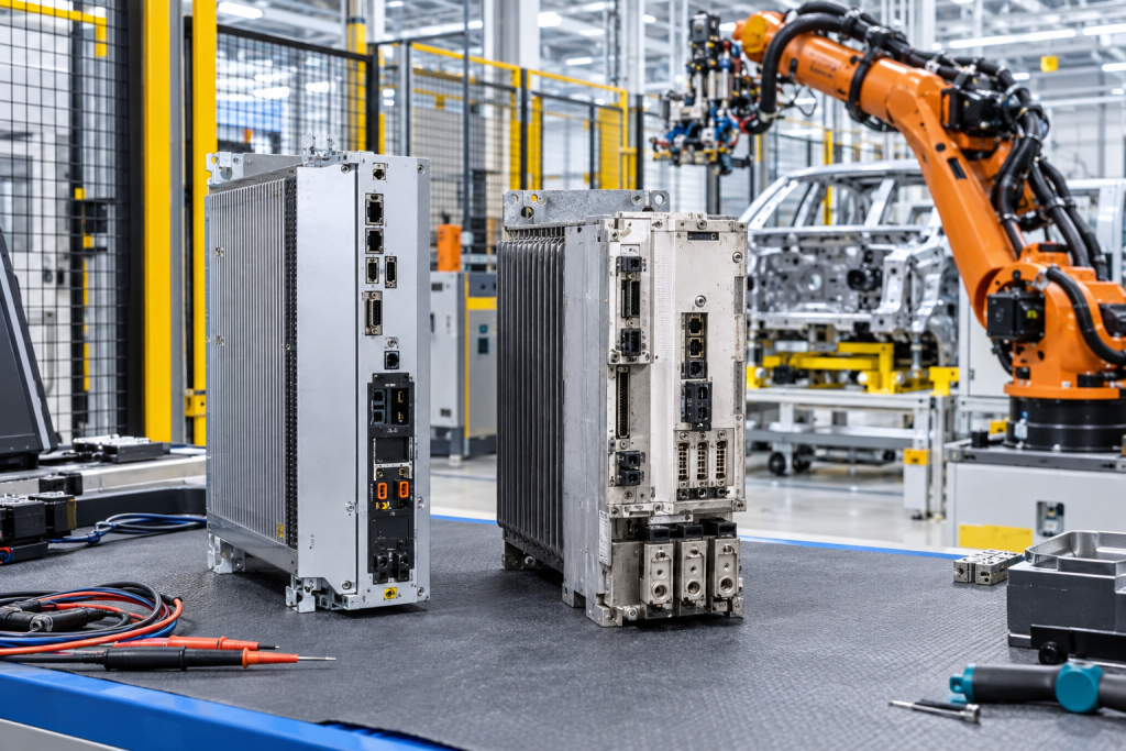
A robot that drops drive enable may show an axis alarm, a controller alarm, or a chain of secondary messages created by one power-stage problem. Under production pressure, it is tempting to search the alarm text and order the first KUKA drive module with a similar rating. That shortcut is especially dangerous when KRC2 and KR C4 hardware are discussed in the same maintenance conversation.
KUKA documentation identifies the KSP as the drive controller for manipulator axes in KR C4 systems, with variants sized for different axis-current groups. KRC2 systems use the earlier KSD amplifier architecture. They solve related motion-control tasks, but they are not interchangeable families and should never share an ambiguous spare description.
First Identify The Controller Generation
Record the cabinet type, controller generation, robot model, serial data, number of axes, supply voltage, drive-bus arrangement, software version, and the exact module position. Photograph the complete cabinet before removing covers, then capture the drive label, connectors, fan path, DC-link connections, and adjacent power modules.
Controller identity must appear at the top of the RFQ. “KUKA servo drive” is not a usable specification. A buyer needs to know whether the plant is working on KRC2 with KSD modules, KR C4 with KSP modules, or another controller variant, because connectors, architecture, diagnostics, and acceptance work differ.
Use Axis Evidence To Avoid Replacing The Wrong Module
Map the alarm to the affected axis or axis group. Record whether the fault follows the module, motor, encoder, cable, or cabinet position after approved diagnostic swaps. Check brake behavior, motor temperature, mechanical resistance, collision history, and whether the fault appears at enable, during motion, or under load.
The KUKA 00-198-266 KSP 600-3×20 servo pack illustrates why current grouping matters. The offer should match the complete part number and variant, not merely “KSP 600.” Ask for photos of the rating label, power connectors, communication interface, cooling surfaces, and condition of the mounting points.
For KRC2, Inspect The Whole KSD Power Path
A KUKA KSD1-16 servo drive amplifier belongs to a system that also depends on supply modules, DC bus, drive bus, resolver or feedback connections, motor cables, cabinet cooling, and safety enable. A drive alarm may be produced by a weak supply, contaminated connector, failed fan, damaged cable, or mechanically blocked axis.
Before replacing the amplifier, check for heat discoloration, loose bus connections, conductive dust, fan failure, and damaged connector locks. Follow site electrical-safety procedures for DC-link discharge and verification. The stored energy inside a robot drive cabinet makes improvised troubleshooting unacceptable.
Preserve Data Before Power Hardware Work
Create a controller archive before the outage and verify that it can be read. Record mastering data, machine data, safety configuration responsibility, tool and base data, fieldbus configuration, and any production programs needed for recovery. Hardware replacement should not become the moment the plant discovers that its only archive is incomplete.
Keep the removed module, fault log, and archive linked to the same work order. If a repaired or exchange unit is installed, record its serial number and the tests performed. This history helps distinguish a recurring external cause from repeated module failure.
Prove Motion In Controlled Stages
After installation, begin with cabinet diagnostics and communication. Confirm DC-link and drive readiness, then test safety enable, brake release, feedback plausibility, low-speed jog, mastering status, and movement in a safe envelope. Increase speed and load only after the basic axis behavior is stable.
The final acceptance should include repeatable motion, absence of abnormal current or temperature behavior, correct safety response, valid fieldbus communication, and a controlled production-cycle test. A cleared alarm at standstill is only the first checkpoint.
Keep KRC2 And KR C4 Records Separate
Plants with several robot generations should maintain controller-specific spare lists even when the cells perform similar work. Use separate locations or unmistakable labels for KSD and KSP hardware, cable sets, archives, and test instructions. The objective is to make the wrong part visibly wrong before anyone carries it to the cell.
Add the responsible automation engineer and the last verified test date to each record. Robot cells change through tooling, software, safety, and fieldbus modifications; a spare qualified years ago may no longer represent the current controller configuration. Periodic review is cheaper than discovering that drift during a production stop.
For high-consequence cells, record one known-good module or controlled test result as the comparison baseline. When a future alarm occurs, technicians can compare connector condition, diagnostic sequence, current behavior, and axis response against evidence from a healthy state instead of relying on memory.
FAQ
Are KSP and KSD drive modules interchangeable?
No. KSP is associated with KR C4 architecture, while KSD modules belong to KRC2 systems. Match the controller generation and full part number.
What photos help identify a KUKA drive spare?
Provide the cabinet overview, complete module label, connector faces, DC-bus connections, cooling surfaces, mounting position, and adjacent modules.
Can a servo-drive alarm be caused by the robot mechanics?
Yes. Brake problems, cable damage, motor or feedback faults, collisions, and mechanical resistance can produce drive symptoms that survive a module replacement.
What should the restart test include?
Check diagnostics, safety enable, brake and feedback behavior, low-speed jog, mastering status, representative loaded motion, fieldbus communication, and a controlled cycle.
Send ZYPLC the KUKA controller generation, robot model, drive labels, axis and alarm history, cabinet photos, archive status, acceptable condition, and recovery deadline for a focused servo-drive inquiry.
© 2026 ZYPLC. All rights reserved. Official Website: https://zyplc.com Inquiry: sales@zyplc.com | WhatsApp/Tel: +86 18359293191