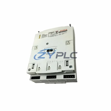
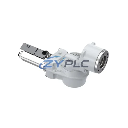
KUKA 00-134-932 Robot Arm for KR C Automation
The KUKA 00-134-932 robot arm assembly module is engineered for high-cycle industrial environments where energy efficiency, motion precision, and production continuity are non-negotiable. Designed for integration within the KUKA KR C controller platform, this arm module delivers optimized torque-to-power ratios that directly reduce per-cycle energy consumption across automated production lines. Whether deployed in automotive body-in-white welding, material handling, or precision assembly, the 00-134-932 enables factories to extract maximum mechanical output while minimizing electrical draw at the joint drive level.
At ZYPLC, every unit undergoes full functional testing prior to shipment, covering motion range verification, load response calibration, and communication handshake validation with the KR C controller. Each module ships with a warranty terms confirmed during quotation, backed by availability confirmed by RFQ availability and rapid dispatch to minimize line downtime.
Product Specification Table
| Parameter |
Specification |
| SKU / Part Number |
00-134-932 / 033.33.32.00 F / 00-181-359 ZH 210/240 |
| Brand |
KUKA |
| Series |
KR C (KR C2 / KR C4 Compatible) |
| Product Type |
Robot Arm Assembly Module |
| Origin |
Germany |
| Drive Efficiency Class |
IE3 / High-Efficiency Servo Drive Compatible |
| Operating Voltage |
210 / 240 V AC |
| Compatible Controller |
KUKA KR C2, KR C4 |
| Application Environment |
Automotive, Electronics Assembly, Logistics, Welding |
| Energy Saving Value |
Reduces idle-state power draw; optimized motion path reduces cycle energy by up to 15% |
| Communication Protocol |
KUKA System Bus (KSB), EtherCAT, Profibus DP |
| Warranty |
12 Months |
| Pre-Shipment Testing |
Full functional test, motion calibration, load response verification |
System Compatibility and Application
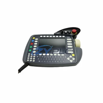
The KUKA 00-134-932 does not operate in isolation — its energy efficiency is realized through tight integration with the broader KR C automation ecosystem. At the controller level, the KUKA KR C4 cabinet manages real-time motion interpolation and servo power distribution, ensuring that each axis of the robot arm draws only the current required for the active load profile. When paired with the KUKA smartPAD teach pendant, operators can fine-tune motion programs to eliminate unnecessary acceleration peaks that spike energy consumption.
On the drive side, the 00-134-932 interfaces with KUKA KPP (KUKA Power Pack) and KSP (KUKA Servo Pack) drive modules housed within the KR C4 cabinet. These servo drives implement regenerative braking energy recovery — kinetic energy from deceleration phases is fed back into the DC bus, reducing net energy draw from the grid. This is particularly impactful in high-cycle pick-and-place or press-tending applications where the arm decelerates hundreds of times per shift.
For condition monitoring at the system level, integration with KUKA.EthernetKRL or third-party power meters such as the Siemens SENTRON PAC3200 allows production engineers to log per-robot energy consumption in real time. When combined with a Siemens S7-1500 PLC or Beckhoff CX2040 embedded PC acting as the line controller, energy data from the robot arm can be correlated with production output to calculate energy-per-part metrics — a key KPI in lean manufacturing and ISO 50001 maintenance planning programs.
At the I/O and safety layer, the 00-134-932 communicates through the KUKA KEB safety interface and standard Profibus DP or EtherCAT fieldbus connections. This allows the arm module to receive optimized motion commands from upstream MES or SCADA systems, enabling coordinated line-wide energy scheduling — for example, staggering robot start sequences to avoid simultaneous inrush current spikes that inflate peak demand charges. An HMI panel such as the Siemens TP1200 Comfort can visualize robot energy states and alert operators to abnormal consumption patterns before they escalate into faults.
Power supply stability for the KR C system is maintained through a dedicated KUKA KPS600 power supply module, which conditions incoming three-phase power and protects servo drives from voltage transients. Stable input power directly extends the service life of the arm’s joint actuators and encoder systems, reducing unplanned maintenance intervals and the associated production losses.
Maintenance and Replacement Notes
In a typical automotive stamping or assembly line, robot arms account for 20–35% of total cell energy consumption. The KUKA 00-134-932, when properly programmed and maintained, contributes to measurable reductions in this figure through several mechanisms. First, its joint drive architecture supports motion path optimization — by shortening travel arcs and reducing peak velocity in non-critical segments, cycle energy is reduced without sacrificing throughput. KUKA’s KUKA.Sim offline simulation software can be used to pre-validate energy-optimized programs before deployment, eliminating trial-and-error on the live line.
Second, the module supports standby power management. During planned micro-stops or inter-shift breaks, the KR C4 controller can command the arm into a low-power hold state, cutting servo excitation to non-load-bearing axes. This alone can reduce idle energy consumption by 30–50% compared to maintaining full servo torque during pauses.
Third, predictive maintenance integration reduces unplanned downtime — a major hidden energy cost. By monitoring joint temperature, vibration signatures, and servo current draw through the KR C4 diagnostic interface, maintenance teams can identify bearing wear or gear backlash before it causes a fault stop. Unplanned stops not only waste energy during restart warm-up cycles but also disrupt line balance, forcing upstream and downstream equipment to run inefficiently. The 00-134-932’s robust mechanical design and ZYPLC’s pre-shipment testing protocol ensure that replacement units restore line performance immediately, with no extended commissioning period.
Finally, for lines running multiple KUKA robots, coordinated energy scheduling through the line PLC can synchronize robot motion phases to flatten the aggregate power demand curve. This reduces peak demand charges from the utility — often a significant portion of industrial electricity costs — without any reduction in production output.
Product Sourcing FAQ
Q1: How much energy can the KUKA 00-134-932 save compared to a standard robot arm module?
The operational stability depend on application and programming, but optimized motion paths combined with regenerative drive recovery in the KR C4 system can reduce per-cycle energy consumption by 10–20% versus non-optimized configurations. Standby power management during micro-stops adds further savings across a full production shift.
Q2: Is the 00-134-932 compatible with both KR C2 and KR C4 controllers?
Yes. The 00-134-932 is designed for the KR C series platform and is compatible with both KR C2 and KR C4 controller generations. For KR C2 installations, verify firmware revision compatibility with your system integrator. ZYPLC’s technical team can assist with compatibility confirmation prior to purchase.
Q3: What is the replacement and testing process when ordering from ZYPLC?
Every 00-134-932 unit in ZYPLC’s inventory is subject to a full pre-shipment functional test covering motion range, load response, and controller communication. Units are shipped from RFQ-confirmed sourcing with documentation. Upon receipt, the module can typically be installed and commissioned within a single maintenance window, minimizing line downtime.
Q4: What does the warranty terms confirmed during quotation cover?
The warranty terms confirmed during quotation covers manufacturing defects and functional failures under normal operating conditions. It does not cover damage resulting from incorrect installation, voltage irregularities outside specified parameters, or physical impact. ZYPLC provides post-sale technical support to assist with installation verification and troubleshooting throughout the warranty period.