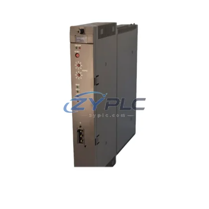
KUKA KPP 600-20 00-160-150 Power Module for KPP/KSP 600
In modern industrial robot control architecture, power supply integrity is the foundation upon which every other system layer depends. The KUKA KPP 600-20 (Part No. 00-160-150) is a dedicated servo power module engineered for seamless integration within the KPP/KSP 600 Series controller platform — one of KUKA’s most widely deployed drive and control architectures across automotive, heavy manufacturing, and process automation environments.
Unlike generic power components, the KPP 600-20 is designed as a system-native module. It operates as the primary DC bus power supply within the KRC4 controller cabinet, delivering regulated intermediate circuit voltage to downstream servo drive modules including the KSP 600-3×20 (00-192-552) and KSP 600-3×40 UL (00-198-268). This tight architectural coupling ensures that current delivery, bus voltage stability, and fault propagation behavior are all governed by KUKA’s integrated control logic — not by external workarounds.
From a system architecture perspective, the KPP 600-20 sits at the intersection of the power layer and the drive layer. It receives three-phase AC input from the cabinet’s power distribution unit, rectifies and conditions it into a stable DC intermediate circuit, and feeds that bus to the KSP servo modules that directly drive the robot’s axis motors. This architecture eliminates the need for separate DC power supplies per axis, reduces cabinet wiring complexity, and enables centralized fault monitoring through the KRC4 controller and its associated KUKA smartPAD teach pendant interface.
The module’s role extends beyond simple power conversion. In multi-robot or extended-reach cell configurations, the KPP 600-20 supports shared DC bus topologies where braking energy from decelerating axes is redistributed across the bus rather than dissipated as heat — improving energy efficiency and reducing thermal load on the cabinet. This regenerative capability is particularly valuable in high-cycle applications such as spot welding lines, press tending, and palletizing systems where axes are in constant motion.
System engineers integrating the KPP 600-20 into new or retrofit installations will find it fully compatible with the standard KRC4 backplane and mounting rail system, allowing it to be installed alongside other KPP/KSP 600 series modules without custom mechanical adaptation. The module communicates fault and status data through the KRC4’s internal EtherCAT-based drive bus, enabling real-time diagnostics from the controller’s WorkVisual engineering environment. This means maintenance teams can identify power module anomalies — such as DC bus undervoltage, overcurrent events, or thermal warnings — without physical inspection of the cabinet interior.
For facilities managing fleets of KUKA robots, the KPP 600-20 represents a critical spare parts inventory item. A single failed power module can halt an entire robot cell, making availability and lead time essential considerations. ZYPLC maintains availability subject to RFQ confirmation of the 00-160-150 with full functional testing prior to shipment, supported by a warranty terms confirmed during quotation covering manufacturing defects and operational failures under normal use conditions. This warranty applies equally to new and refurbished units and is backed by documented test records available upon request.
The module’s system integration capability means it is not supplied as an isolated component but as part of a broader system support framework. ZYPLC’s technical team can assist with compatibility verification against specific KRC4 cabinet configurations, advise on pairing with the correct KSP 600 servo modules for a given robot model, and provide guidance on installation sequencing to minimize downtime during replacement procedures.
Product Specification Table
| Parameter |
Specification |
| Part Number |
00-160-150 |
| Model |
KPP 600-20 |
| Brand |
KUKA |
| Series |
KPP/KSP 600 |
| System Role |
DC Bus Power Supply Module (Servo Power Pack) |
| Compatible Controller |
KUKA KRC4 |
| AC Input Voltage |
3 × 400/480 V AC, 50/60 Hz |
| DC Intermediate Circuit Output |
600 V DC Bus |
| Rated Current |
20 A (continuous) |
| Communication Interface |
EtherCAT (internal KRC4 drive bus) |
| Installation |
DIN rail / KRC4 cabinet backplane mount |
| Cooling |
Forced air (cabinet-integrated fan system) |
| Operating Temperature |
0°C to +45°C (cabinet ambient) |
| Country of Origin |
Germany |
| Warranty |
warranty terms confirmed during quotation (manufacturing defects & operational failure) |
| system integration |
Verified compatible with KRC4 architecture; system-level support available |
System Compatibility Notes
The KPP 600-20 does not operate in isolation — its value is realized through its role within a coordinated drive and control architecture. In a standard KRC4-based robot cell, the power module works in direct coordination with the following system components:
The KSP 600-3×20 (00-192-552) and KSP 600-3×40 UL (00-198-268) servo drive modules receive their DC bus supply directly from the KPP 600-20, making the power module the upstream dependency for all axis motion. Any instability in the KPP’s output is immediately reflected in axis performance, which is why module integrity is a primary diagnostic checkpoint during robot fault analysis.
The KUKA KRC4 controller cabinet provides the supervisory control layer, executing motion programs, managing safety zones, and coordinating communication between the robot and external PLCs or SCADA systems via PROFINET or EtherNet/IP fieldbus interfaces. The KPP 600-20 reports its operational status to the KRC4 in real time, enabling the controller to initiate controlled shutdowns or fault recovery sequences without operator intervention.
The KUKA smartPAD teach pendant serves as the human-machine interface layer, providing operators with access to drive status, power module diagnostics, and axis enable/disable functions. When a KPP 600-20 fault is detected, the smartPAD displays structured error codes that guide maintenance personnel directly to the affected module.
At the cabinet infrastructure level, the KRC4 power distribution board and associated 24 V DC logic power supply provide the auxiliary power rail that keeps the controller and safety circuits active even when the main drive bus is de-energized — a critical feature for safe maintenance access. The KRC4 safety controller (KSC) monitors the drive enable chain and ensures the KPP 600-20 cannot energize the DC bus unless all safety conditions are satisfied.
For extended robot configurations or multi-axis systems, additional KPP 600-20 modules can be paralleled on the same DC bus to increase available current capacity, while KSP 600 series braking resistor modules manage regenerative energy during high-deceleration cycles. This modular scalability is a defining characteristic of the KPP/KSP 600 platform and a key reason it remains in active deployment across KUKA’s KR QUANTEC, KR AGILUS, and KR CYBERTECH robot families.
Industrial Application Notes
The KPP 600-20 is deployed across a wide range of industrial automation environments where KUKA robots form part of a larger, multi-layer control architecture.
In automotive body-in-white manufacturing, KRC4-based robot cells equipped with KPP 600-20 modules handle spot welding, seam sealing, and component handling at cycle times measured in seconds. The power module’s ability to support regenerative braking across shared DC bus configurations reduces energy consumption per weld cycle and lowers cabinet operating temperatures in high-density robot installations.
In electrical and electronics manufacturing, precision assembly robots using the KRC4 platform rely on the KPP 600-20’s stable DC bus output to maintain sub-millimeter positioning repeatability. Any voltage ripple or transient on the intermediate circuit directly affects servo loop performance, making power module quality a direct determinant of process quality.
In food and beverage packaging lines, KRC4 robots performing pick-and-place, case packing, and palletizing operations run continuously across multiple shifts. The KPP 600-20’s robust thermal design and compatibility with the KRC4’s predictive maintenance framework allow facilities to schedule power module inspections based on operating hours rather than reactive fault response.
In heavy industry and foundry applications — including die casting, forging, and metal forming — robots operating in high-vibration, high-temperature environments place additional stress on power electronics. The KPP 600-20’s industrial-grade construction and KUKA’s system-level thermal management ensure reliable operation in these demanding conditions.
For system integrators and OEM machine builders, the KPP 600-20’s standardized form factor and EtherCAT integration simplify cabinet design and reduce commissioning time. Compatibility with KUKA’s WorkVisual configuration software means drive parameters, bus topology, and fault response behaviors can be configured, documented, and replicated across multiple identical robot cells without manual reconfiguration.
Product Compatibility FAQ
Q1: Is the KPP 600-20 (00-160-150) compatible with all KRC4 controller variants, and can it be used with both KSP 600-3×20 and KSP 600-3×40 UL servo modules?
The KPP 600-20 is designed for the KRC4 controller platform and is compatible with the standard KRC4, KRC4 compact, and KRC4 smallsize cabinet variants that use the KPP/KSP 600 series drive architecture. It operates as the DC bus source for both the KSP 600-3×20 (00-192-552) and KSP 600-3×40 UL (00-198-268) servo modules. Before installation, verify the cabinet’s bus configuration and rated current requirements against the total axis load to ensure the KPP 600-20’s 20 A continuous rating is sufficient for your specific robot model and payload configuration.
Q2: What does the warranty terms confirmed during quotation cover, and what support is available for installation and commissioning?
The warranty terms confirmed during quotation covers manufacturing defects and operational failures occurring under normal operating conditions as defined by KUKA’s installation and environmental specifications. It applies from the date of shipment and includes replacement or repair of the module at ZYPLC’s discretion. All units are functionally tested prior to dispatch, with test records available upon request. ZYPLC’s technical team provides pre-sale compatibility verification, installation guidance, and post-installation support to assist with commissioning within the KRC4 architecture. system integration support — including advice on bus configuration, module pairing, and WorkVisual parameter setup — is available as part of the purchase process.
Q3: How should the KPP 600-20 be replaced in a live production environment to minimize downtime, and what are the key post-replacement commissioning steps?
Replacement of the KPP 600-20 should be performed with the KRC4 controller in a safe, de-energized state with the main disconnect locked out. After physical installation, the replacement module must be recognized by the KRC4’s drive bus configuration — in most cases this occurs automatically via EtherCAT enumeration, but WorkVisual should be used to verify the drive topology matches the cabinet’s configuration file. Key post-replacement checks include DC bus voltage verification, drive enable chain continuity, and a low-speed axis motion test across all robot axes before returning the cell to production. ZYPLC recommends retaining the replaced module for root cause analysis to determine whether the failure was an isolated event or indicative of a broader cabinet environmental issue.