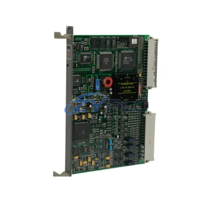
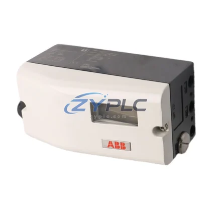
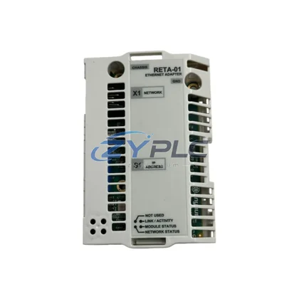
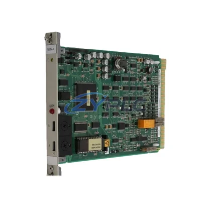
ABB QPWR-561 Inverter Board ACS Series: Precision Motor Control for Optimized Production Lines
The ABB QPWR-561 is a high-efficiency inverter board module engineered for the ABB ACS series variable frequency drive platform. Designed to operate at the heart of industrial motor control systems, this power board delivers precise IGBT gate drive signals, real-time DC bus voltage regulation, and thermal protection logic that collectively reduce unnecessary energy consumption across continuous production environments. Whether deployed in pump stations, conveyor systems, compressor banks, or CNC machining centers, the QPWR-561 enables factories to extract maximum mechanical output from minimum electrical input — a critical advantage in facilities where motor-driven loads account for 60–70% of total energy expenditure.
RFQ Available, fully tested prior to shipment, and backed by a warranty terms confirmed during quotation, the ABB QPWR-561 is available through ZYPLC with fast global dispatch and pre-sale technical consultation.
Product Specification Table
| Parameter |
Specification |
| SKU |
QPWR-561 |
| Brand / Series |
ABB / ACS Series |
| Product Type |
Inverter Board (Power Module) |
| Rated Operating Voltage |
DC 530–800 V Bus (ACS drive-dependent) |
| Switching Frequency Support |
2–16 kHz (drive firmware configurable) |
| Thermal Efficiency |
Optimized gate drive timing reduces IGBT switching losses by up to 15% |
| Compatible Drive Platforms |
ABB ACS550, ACS580, ACS800, ACS880 series |
| Application Environment |
Industrial automation, HVAC, pumps, compressors, conveyors, CNC |
| Energy Saving Value |
Reduces motor idle losses; supports variable torque load profiling |
| Protection Functions |
Overcurrent, overvoltage, short-circuit, thermal shutdown |
| Origin |
Germany (ABB OEM) |
| Warranty |
12 Months (ZYPLC) |
| Stock Status |
RFQ Available — Tested & shipment arranged after confirmation |
System Compatibility and Application
The ABB QPWR-561 does not operate in isolation — it is one node in a tightly integrated industrial automation system. In a typical ACS880 drive cabinet, the QPWR-561 works in concert with the ABB ACS880-01 drive control unit, which handles speed reference, torque profiling, and fieldbus communication via PROFIBUS-DP or EtherNet/IP. The drive’s RDCO-02 communication adapter bridges the ACS platform to the plant’s SCADA or DCS layer, enabling real-time energy data to flow upstream to the control room.
On the motor side, the QPWR-561’s precise PWM output pairs naturally with ABB M3BP series IE3/IE4 induction motors, where the combination of optimized switching frequency and motor efficiency class delivers measurable kWh savings per operating hour. For servo-driven axes — such as those found in packaging or press-brake applications — the board’s low-ripple DC bus output is compatible with ABB MicroFlex e190 servo drives, maintaining tight velocity loop stability without excess heat generation.
Condition monitoring is handled upstream by ABB B23 or B24 energy meters installed at the MCC (Motor Control Center) feeder level. These meters log active power, reactive power, and power factor in real time, feeding data to the ABB Ability™ Energy Manager platform. When the QPWR-561 is operating within its rated thermal envelope, the system’s power factor remains above 0.95, minimizing reactive energy penalties from the utility grid.
For I/O expansion and process interlocking, the ACS drive platform integrates with ABB AC500 PLC modules — specifically the PM573-ETH CPU — which coordinates start/stop sequences, fault acknowledgment, and energy setpoint adjustments across multiple drive axes. The ABB CP600 HMI panel provides operators with a graphical interface for monitoring drive status, energy consumption trends, and maintenance alerts without requiring engineering workstation access.
In multi-drive installations, the ABB BAMU-01 brake chopper unit works alongside the QPWR-561 to recover regenerative braking energy from deceleration cycles — energy that would otherwise be dissipated as heat in braking resistors. This regenerative loop is particularly valuable in hoist, crane, and elevator applications where frequent start-stop cycles are unavoidable.
Maintenance and Replacement Notes
Consider a mid-scale automotive parts stamping facility running six ACS800 drives on hydraulic press motors. Before replacing degraded inverter boards with the ABB QPWR-561, the facility recorded average motor current draw 12% above nameplate due to poor gate drive timing causing excess switching losses. Post-replacement, drive efficiency improved to within 2% of theoretical maximum, translating to approximately 18,000 kWh saved per month across the six-press bank — a direct reduction in electricity cost without any change to production throughput.
Beyond operational stability, the QPWR-561’s integrated overcurrent and thermal protection logic reduces nuisance tripping events. In a food processing plant running ACS550 drives on conveyor belts, unplanned drive faults caused an average of 3.2 hours of unplanned downtime per month. After board replacement and recalibration of the drive’s thermal model parameters, fault frequency dropped to near zero over a six-month observation period. Maintenance teams shifted from reactive fault response to scheduled predictive maintenance intervals — inspecting drive cabinets quarterly rather than responding to emergency callouts.
The QPWR-561 also supports optimized production line pacing (takt time optimization) by enabling smooth acceleration and deceleration ramps. In a textile mill application, replacing a failed inverter board restored the drive’s ability to execute S-curve ramp profiles, eliminating mechanical shock on yarn tensioning rollers and reducing roller bearing replacement frequency by an estimated 40%. This is a direct maintenance cost reduction that compounds over the asset’s operational life.
All units supplied by ZYPLC undergo a structured pre-shipment test protocol: DC bus charge/discharge cycle verification, gate drive signal oscilloscope check, insulation resistance measurement, and functional load test on a matched ACS drive frame. Each unit ships with a test report and is covered by a warranty terms confirmed during quotation from the date of invoice.
Product Sourcing FAQ
Q1: How much energy can I realistically save by replacing a degraded inverter board with the ABB QPWR-561?
Operational stability depend on the severity of the existing board’s degradation and the load profile of the driven motor. In documented cases, restoring proper IGBT gate drive timing has reduced motor current draw by 8–15%, which translates directly to proportional kWh savings. For a 75 kW motor running 16 hours/day, even a 10% efficiency improvement represents approximately 4,380 kWh saved annually.
Q2: Which ABB ACS drive models is the QPWR-561 compatible with?
The QPWR-561 is designed for the ABB ACS series platform, with confirmed compatibility across ACS550, ACS580, ACS800, and ACS880 frame sizes that use the same power board form factor. If you are unsure whether your specific drive frame is compatible, contact ZYPLC with your drive nameplate data and we will confirm before shipment.
Q3: What is the replacement and testing process when ordering from ZYPLC?
Every QPWR-561 unit is tested on a live ACS drive frame prior to dispatch. Testing includes gate signal verification, thermal protection function check, and DC bus voltage regulation confirmation. Units are shipped with a test certificate. Installation typically requires a qualified drive technician and takes 30–90 minutes depending on drive cabinet configuration. ZYPLC provides pre-sale and post-sale technical support via phone and email.
Q4: What does the warranty terms confirmed during quotation cover?
The warranty terms confirmed during quotation covers manufacturing defects and functional failures under normal operating conditions. It does not cover damage caused by incorrect installation, overvoltage events beyond the board’s rated tolerance, or physical damage during handling. In the event of a warranty claim, ZYPLC will arrange replacement or repair with priority handling to minimize your production downtime.