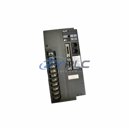
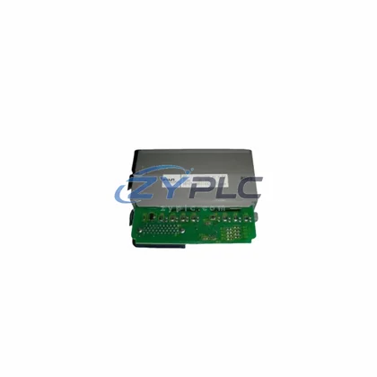
Fuji SA531121-03-E11-C4 Drive Board: Coordination for FRENIC Series
In modern industrial automation, no component operates in isolation. The Fuji Electric SA531121-03-E11-C4 PCB Drive Board is engineered as a precision control element within the FRENIC Series variable frequency drive (VFD) platform, serving as the critical interface between the control layer and the power conversion layer. Understanding this board’s role requires examining the full system architecture — from the CPU and I/O modules at the top of the control hierarchy down through the power stage, motor feedback loops, and field-level actuators.
The SA531121-03-E11-C4 is specifically designed for FRENIC-E11 and FRENIC-C4 series drives, two of Fuji Electric’s most widely deployed VFD families in process control, HVAC, pump and fan applications, and general-purpose manufacturing lines. As a drive board, it governs gate signal generation, PWM modulation logic, and feedback signal conditioning — functions that are foundational to stable motor control across variable load conditions.
Product Specification Table
| Parameter |
Specification |
| Part Number |
SA531121-03 |
| Compatible Series |
FRENIC-E11 / FRENIC-C4 |
| System Role |
PCB Drive Board (Gate Control / PWM Signal Layer) |
| Board Type |
Drive Control PCB Module |
| Electrical Interface |
Internal VFD bus connector, multi-pin ribbon interface |
| Signal Function |
PWM gate drive, feedback conditioning, fault detection |
| Communication Capability |
Internal drive bus; compatible with FRENIC control card stack |
| Installation Environment |
Enclosed VFD cabinet, DIN-rail or panel-mount drive chassis |
| Origin |
Japan |
| Warranty |
warranty terms confirmed during quotation (functional test verified) |
System Compatibility Notes
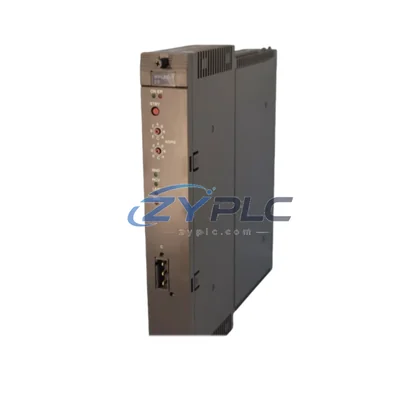
The SA531121-03-E11-C4 does not function as a standalone unit — it is one layer in a tightly coordinated drive system. In a typical FRENIC-based automation architecture, the drive board works in concert with the FRENIC-E11 main control card, which handles speed reference processing, PID loop execution, and communication protocol management. Above the drive level, a Fuji Electric MICREX-SX series PLC or a third-party Modbus RTU master provides setpoint commands and monitors drive status via RS-485 or optional fieldbus cards.
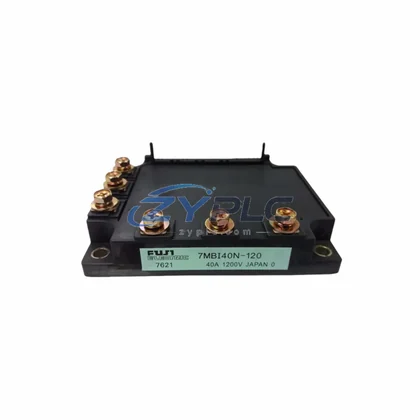
On the power side, the SA531121-03-E11-C4 interfaces directly with the IGBT power module assembly within the FRENIC-C4 chassis, translating logic-level gate signals into high-current switching events. Proper coordination between the drive board and the power module is essential for maintaining switching frequency stability, minimizing harmonic distortion, and protecting the motor winding insulation over long operational cycles.
At the I/O layer, the FRENIC-E11 platform supports expansion via optional I/O extension cards such as the OPC-E1-DIO digital I/O card and the OPC-E1-AIO analog I/O card, which feed process signals — pressure, flow, temperature — into the drive’s internal PID controller. The SA531121-03-E11-C4 drive board ensures that these analog and digital references are accurately translated into motor speed commands without signal degradation.
For multi-drive systems, the FRENIC-C4 series supports master-follower configurations using the built-in RS-485 port and optional PROFIBUS-DP or DeviceNet communication cards. In these architectures, the drive board in each follower unit must maintain synchronous gate timing with the master drive — a function that depends on the integrity of the SA531121-03-E11-C4 PCB. Replacing a faulty drive board with a verified OEM unit is therefore critical to restoring synchronization accuracy in multi-motor conveyor, winding, or draw-roll applications.
At the human-machine interface layer, operators interact with the drive system through the Fuji Electric TP-E1U keypad panel or a remote HMI connected via the drive’s RS-485 port. Parameter changes made at the HMI level — acceleration ramps, frequency limits, torque boost settings — are executed by the control card and ultimately realized through the gate signals generated by the SA531121-03-E11-C4 drive board. A malfunctioning drive board can cause erratic motor behavior even when all upstream parameters are correctly configured, making accurate board identification and replacement essential for efficient fault resolution.
For redundancy-critical applications, engineers may deploy hot-standby drive configurations using bypass contactors and redundant FRENIC-C4 units. In such designs, maintaining an inventory of verified SA531121-03-E11-C4 boards ensures that mean time to repair (MTTR) remains within acceptable limits, minimizing production downtime during unplanned drive failures.
Industrial Application Notes
The SA531121-03-E11-C4 drive board sees deployment across a broad range of industrial sectors. In water and wastewater treatment facilities, FRENIC-E11 drives control submersible pump motors and blower fans, where consistent PWM performance directly affects energy efficiency and process stability. In petrochemical and refinery applications, FRENIC-C4 drives manage compressor and agitator motors in hazardous-area control panels, where drive board reliability is a safety-critical requirement.
In metal processing and rolling mill environments, multi-drive FRENIC systems coordinate tension control across multiple motor axes. The drive board’s gate signal precision determines the quality of speed matching between upstream and downstream rolls. Similarly, in packaging and converting lines, FRENIC-E11 drives handle web tension, registration, and cut-to-length functions where millisecond-level response accuracy is required.
For HVAC and building automation applications, FRENIC-C4 drives are commonly integrated with BACnet or Modbus-based building management systems. The SA531121-03-E11-C4 board supports the drive’s ability to respond to variable air volume (VAV) and variable water volume (VWV) control signals with the precision required for energy-optimized operation under ASHRAE standards.
Product Compatibility FAQ
Q1: Is the SA531121-03-E11-C4 compatible with both FRENIC-E11 and FRENIC-C4 series drives?
Yes. The SA531121-03-E11-C4 PCB drive board is designed for use across the FRENIC-E11 and FRENIC-C4 drive families. Before installation, verify the drive’s nameplate model code and cross-reference with the board’s connector layout to confirm mechanical and electrical compatibility. If you are unsure, contact our technical team with your drive’s full model number for confirmation.
Q2: What does the warranty terms confirmed during quotation cover, and how does it support long-term maintenance planning?
Our warranty terms confirmed during quotation covers functional defects in the SA531121-03-E11-C4 board under normal operating conditions. Each board is tested prior to shipment to verify gate signal output, feedback circuit integrity, and connector continuity. For maintenance engineers managing multi-site drive inventories, this warranty provides a reliable baseline for spare parts planning and reduces the risk associated with sourcing replacement boards for aging FRENIC installations.
Q3: How should the SA531121-03-E11-C4 be installed to ensure system-level compatibility and avoid commissioning issues?
Installation should follow Fuji Electric’s FRENIC series service manual procedures. Power down the drive completely and discharge the DC bus capacitors before removing or installing the drive board. Ensure all ribbon connectors are fully seated and locked. After installation, perform a no-load test run to verify PWM output stability before reconnecting the motor. Parameter settings stored in the control card are not affected by drive board replacement, simplifying recommissioning in most applications.