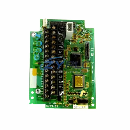
KUKA KPP 600-20 2×40 00-198-263 Power Driver for KRC Series
The KUKA KPP 600-20 2×40 (Part No. 00-198-263) is a dual-axis servo power driver module engineered for seamless integration within the KUKA KRC robot controller architecture. Rather than functioning as a standalone component, this module occupies a critical position within the layered automation hierarchy — bridging the control layer commanded by the KRC CPU unit and the execution layer driven by KUKA servo motors. Its role is to convert DC bus power into precisely regulated drive signals for two servo axes simultaneously, enabling synchronized, high-torque motion across multi-axis robotic systems deployed in demanding industrial environments.
In a complete KUKA KRC-based control system, the KPP 600-20 2×40 works in close coordination with multiple subsystem layers. At the control layer, the KRC4 or KRC2 controller cabinet houses the primary CPU and motion planning unit, which dispatches real-time trajectory commands via the internal KUKA System Bus (KSB) or EtherCAT-based communication backbone. The KPP module receives these commands and translates them into precise PWM drive signals for the connected servo axes. This tight coupling between the controller and the power driver ensures deterministic motion response, which is essential for path accuracy in arc welding, material handling, and precision assembly applications.
At the power layer, the KPP 600-20 2×40 interfaces directly with the KUKA KPS 600 power supply module, which provides the regulated DC bus voltage required for servo operation. The KPS 600 acts as the energy backbone of the drive cabinet, and the KPP module draws from this shared bus to power both axes without requiring independent rectification stages. This shared-bus architecture reduces cabinet footprint, simplifies thermal management, and supports energy recovery during deceleration phases — a key advantage in high-cycle robotic applications.
The I/O and signal layer is managed through the KUKA RDC (Resolver-to-Digital Converter) card, which collects encoder and resolver feedback from each servo motor and relays position data back to the KPP and KRC CPU in real time. This closed-loop feedback architecture ensures that the KPP 600-20 2×40 can maintain precise torque and velocity control even under variable load conditions. The RDC card, typically mounted within the robot arm or base, communicates with the drive cabinet via a dedicated resolver cable harness, forming a robust signal chain from motor to controller.
For system redundancy and fault isolation, the KPP 600-20 2×40 supports integration with KUKA’s SafeOperation and SafeRobot software packages when paired with compatible KRC4 controllers and safety-rated I/O modules such as the KUKA KSI (Safety Interface) module. In safety-critical environments — including automotive body-in-white lines and collaborative robot cells — this redundancy architecture allows the system to perform safe torque-off (STO) and safe stop (SS1/SS2) functions without requiring external safety relays, reducing wiring complexity and improving response time.
At the network and communication layer, the KRC controller cabinet integrates with plant-level PROFINET, EtherNet/IP, or DeviceNet networks through dedicated fieldbus gateway modules. The KPP 600-20 2×40 itself does not require direct network configuration, as all motion commands are routed through the KRC CPU. However, its operational status — including drive fault codes, thermal warnings, and axis enable states — is accessible via the KUKA smartPAD HMI or through OPC-UA data channels exposed by the KRC4 controller, enabling remote diagnostics and predictive maintenance integration.
The human-machine interface layer in a KUKA KRC system is anchored by the KUKA smartPAD teach pendant, which provides operators with direct access to drive status, axis configuration, and fault history. When the KPP 600-20 2×40 generates a fault — such as overcurrent, overvoltage, or thermal overload — the smartPAD displays the corresponding error code and recommended corrective action, significantly reducing mean time to repair (MTTR) in production environments. This integration between the drive module and the HMI layer is a defining characteristic of KUKA’s closed-loop system architecture.
From a maintenance and lifecycle perspective, the KPP 600-20 2×40 is designed for hot-swap replacement within the KRC drive cabinet, provided the system is safely de-energized and locked out. Its modular form factor allows technicians to replace a failed drive axis without disturbing adjacent modules such as the KMD (KUKA Motor Drive) or KPS power supply, minimizing downtime during unplanned maintenance events. Paired with a structured spare parts inventory strategy — including keeping one KPP unit per robot cell as a critical spare — facilities can achieve sub-hour recovery times for drive-related failures.
Product Specification Table
| Parameter |
Specification |
| Part Number |
00-198-263 |
| Model |
KPP 600-20 2×40 |
| Brand |
KUKA |
| System Role |
Dual-Axis Servo Power Driver Module |
| Compatible Controllers |
KUKA KRC2, KRC4 Series |
| DC Bus Input Voltage |
600 V DC (nominal) |
| Axis Output Current |
2 × 40 A continuous |
| Communication Interface |
KUKA System Bus (KSB) / EtherCAT |
| Feedback Interface |
Resolver / RDC Card |
| Mounting |
DIN Rail / KRC Drive Cabinet Slot |
| Operating Temperature |
0°C to +45°C |
| Protection Class |
IP20 (cabinet-mounted) |
| Country of Origin |
Germany |
| Warranty |
warranty terms confirmed during quotation |
| system integration |
Supported — KRC Architecture Native |
System Compatibility Notes
The KPP 600-20 2×40 achieves its full performance potential only when deployed within a correctly specified KUKA KRC system architecture. A typical six-axis KUKA robot installation will include the KRC4 controller cabinet as the central processing unit, the KPS 600 shared DC bus power supply, and one or more KPP drive modules — each handling two servo axes. For a six-axis robot, three KPP 600-20 2×40 modules are typically installed in the drive cabinet, with each module managing one pair of robot joints.
The KUKA KMD (KUKA Motor Drive) modules may also be present in larger or extended-axis configurations, such as those involving external linear tracks or rotary positioners. In these architectures, the KPP and KMD modules share the same DC bus supplied by the KPS 600, and all drive modules communicate with the KRC4 CPU through the internal EtherCAT ring. The KUKA RDC card, mounted in the robot arm, collects resolver signals from all six motors and transmits position data back to the drive cabinet via a single multi-core cable, simplifying installation and reducing potential failure points.
For system-level redundancy in critical applications, the KRC4 controller supports integration with external safety PLCs via the KUKA KSI safety interface module, enabling cross-monitoring between the robot controller and plant safety systems. The KUKA smartPAD HMI provides the operator interface for drive configuration, fault acknowledgment, and axis jogging, while the KUKA WorkVisual engineering software enables offline configuration, drive parameter backup, and firmware management across all modules in the cabinet. This end-to-end toolchain — from KPS power supply through KPP drive modules to smartPAD HMI — defines the system integration capability that makes KUKA KRC systems a preferred choice for high-availability automation lines.
Industrial Application Notes
The KUKA KPP 600-20 2×40 is deployed across a wide range of industrial automation sectors where multi-axis servo control, system reliability, and long-term maintainability are paramount. In automotive manufacturing, this module is a standard component in body-in-white welding lines, where KUKA KR QUANTEC and KR AGILUS robots perform spot welding, arc welding, and material handling tasks at cycle times below 10 seconds. The dual-axis drive capability of the KPP 600-20 2×40 allows a single module to control two robot joints simultaneously, reducing cabinet complexity and improving thermal efficiency in high-duty-cycle environments.
In the electronics and semiconductor industry, KUKA robots equipped with KPP 600-20 2×40 drive modules are used for precision pick-and-place, PCB handling, and cleanroom assembly tasks. The low-ripple current output of the KPP module ensures smooth, vibration-free motion at low speeds — a critical requirement for handling fragile components. In food and beverage processing, the module supports hygienic robot designs where the KRC4 controller cabinet is located remotely from the robot arm, with the KPP drive module managing axis control over extended cable runs without signal degradation.
In the energy sector — including wind turbine assembly, solar panel manufacturing, and power plant maintenance — KUKA robots with KRC4 controllers and KPP 600-20 2×40 drive modules are deployed for heavy-payload handling and precision positioning tasks. The module’s ability to deliver 40 A continuous per axis supports high-torque applications involving large robot arms such as the KUKA KR FORTEC series. In mining and metallurgy, where ambient temperatures and vibration levels exceed standard industrial norms, the KPP module’s robust design and cabinet-mounted IP20 protection class ensure reliable operation when installed in properly conditioned control enclosures.
Product Compatibility FAQ
Q1: Is the KUKA KPP 600-20 2×40 (00-198-263) compatible with both KRC2 and KRC4 controller generations?
The KPP 600-20 2×40 with part number 00-198-263 is primarily associated with the KUKA KRC2 drive cabinet architecture. While the physical form factor and DC bus interface share similarities with KRC4 drive components, direct cross-generation substitution is not recommended without consulting KUKA’s compatibility documentation or a qualified KUKA system integrator. For KRC4 systems, verify the exact KPP variant required using the robot’s BOM or the KUKA spare parts portal before ordering.
Q2: What is the recommended installation procedure for replacing a KPP 600-20 2×40 in a live production environment?
Replacement of the KPP 600-20 2×40 must be performed with the KRC controller cabinet fully de-energized and locked out per LOTO (Lockout/Tagout) procedures. After physical replacement, the KRC controller will typically auto-detect the new drive module during boot-up. However, it is recommended to perform a drive parameter restore using KUKA WorkVisual to ensure axis-specific tuning data is correctly applied. Full functional testing — including axis referencing, load test, and safety function verification — should be completed before returning the robot to production. Our warranty terms confirmed during quotation covers manufacturing defects identified during this commissioning phase.
Q3: How does the warranty terms confirmed during quotation apply to the KPP 600-20 2×40, and what does system integration support include?
Every KPP 600-20 2×40 (00-198-263) supplied by ZYPLC is covered by a warranty terms confirmed during quotation against manufacturing defects and premature component failure under normal operating conditions. system integration support means our technical team can assist with system-level compatibility verification — confirming that the KPP module is correctly matched to your KRC controller variant, DC bus configuration, and axis assignment — before shipment. This reduces the risk of installation errors and ensures the module performs as expected within your specific robot architecture from day one.