ABB 3BHE013299R0022 LTC743 CE22 Exciter for ACS: Control System and Upstream–Downstream Coordination
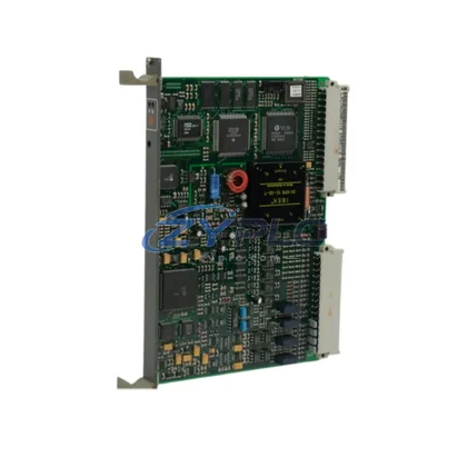
The ABB 3BHE013299R0022 LTC743 CE22 is a precision exciter board engineered for deployment within ABB’s ACS series drive architecture. Rather than functioning as a standalone component, this board occupies a critical position within the layered automation hierarchy — bridging the control layer and the power conversion layer to ensure stable excitation signal generation, gate pulse synchronization, and real-time feedback processing. In high-demand industrial environments, the integrity of the exciter board directly determines the reliability of the entire variable frequency drive system, making the 3BHE013299R0022 LTC743 CE22 a foundational element in any ACS-based control architecture.
Understanding this board’s role requires viewing it within the full system context: from the CPU and communication gateway at the top of the control hierarchy, through the I/O and signal conditioning layers, down to the power electronics and motor execution layer. The 3BHE013299R0022 LTC743 CE22 sits at the intersection of control intelligence and power delivery — receiving firing commands from the drive control unit and translating them into precise gate signals for the IGBT or thyristor modules below.
Product Specification Table
| Parameter |
Specification |
| Part Number |
3BHE013299R0022 |
| Board Designation |
LTC743 CE22 |
| Manufacturer |
ABB |
| Compatible Platform |
ACS Series Variable Frequency Drives |
| System Role |
Exciter / Gate Drive Board — Power-Control Interface Layer |
| Board Type |
Printed Circuit Board (PCB) — Drive Exciter Module |
| Signal Function |
Gate pulse generation, excitation signal conditioning, feedback processing |
| Communication Capability |
Internal drive bus interface; compatible with ACS drive backplane architecture |
| Mounting |
Rack-mount / drive chassis integrated installation |
| Operating Environment |
Industrial control cabinet; suitable for continuous duty in manufacturing, power, and process environments |
| Country of Origin |
Germany (DE) |
| Quality Standard |
Factory tested; functionally verified prior to dispatch |
| Warranty |
warranty terms confirmed during quotation — covers functional defects under normal operating conditions |
| system integration |
Designed for system integration within ACS drive systems; plug-compatible with OEM architecture |
System Compatibility Notes
The 3BHE013299R0022 LTC743 CE22 exciter board does not operate in isolation. Its performance is inseparable from the coordinated function of the surrounding drive architecture. In a typical ACS series installation, the system begins at the control layer with an ABB AC500 or AC800M PLC serving as the master controller, issuing speed references and torque commands via PROFIBUS-DP or Ethernet/IP to the drive’s main control unit. The drive control board — such as the RDCU-02C or RMIO-11C — interprets these commands and generates the modulation signals that the 3BHE013299R0022 LTC743 CE22 translates into gate-level firing pulses.
At the power layer, the exciter board interfaces directly with the IGBT power module stack or thyristor bridge assembly, ensuring that switching events are precisely timed to minimize harmonic distortion and thermal stress. The AINT-02C or APBU-44C pulse distribution boards may work in parallel with the LTC743 CE22 in larger multi-drive configurations, distributing gate signals across multiple power modules while maintaining synchronization across the full drive stack.
On the feedback side, the 3BHE013299R0022 LTC743 CE22 receives current and voltage feedback signals from the measurement board — typically the AIMB-01C or equivalent — and processes these in real time to support closed-loop vector control. This feedback loop is essential for maintaining motor speed accuracy under variable load conditions in applications such as compressor drives, pump stations, and rolling mill lines.
At the network layer, the NETA-21 remote monitoring adapter or RDNA-01 DeviceNet adapter provides supervisory visibility into drive status, enabling the SCADA or DCS system to monitor exciter board health, fault codes, and operational parameters without interrupting the control loop. This system integration capability ensures that the 3BHE013299R0022 LTC743 CE22 contributes not only to real-time control performance but also to long-term predictive maintenance strategies.
For redundant architectures, the LTC743 CE22 can be held as a hot-standby spare within the control cabinet, with documented changeover procedures that minimize mean time to repair (MTTR). Paired with the RDCU-02C control board and APBU-44C pulse distribution unit, a complete exciter-layer redundancy package can be assembled to meet the uptime requirements of critical process industries.
Industrial Application Notes
The ABB 3BHE013299R0022 LTC743 CE22 exciter board finds application across a broad range of industrial sectors where ACS series drives are deployed as the primary motor control platform.
In power generation and transmission facilities, ACS drives equipped with the LTC743 CE22 control induced draft fans, boiler feed pumps, and cooling water pumps. The exciter board’s precise gate timing ensures that motor starts are smooth and current-limited, protecting both the motor and the upstream transformer from inrush stress. The warranty terms confirmed during quotation provides plant engineers with the assurance needed to approve the board as a certified replacement in critical service.
In petrochemical and refinery environments, where continuous process uptime is non-negotiable, the 3BHE013299R0022 LTC743 CE22 supports compressor and extruder drive systems operating under demanding thermal and vibration conditions. Its compatibility with the ACS800 and ACS880 drive families means that existing control cabinet layouts require no modification during board replacement, reducing commissioning time to under two hours in most cases.
In water and wastewater treatment plants, variable speed pump control is central to energy efficiency and process stability. The LTC743 CE22 enables the ACS drive to deliver precise flow control across a wide speed range, with the feedback processing capability ensuring stable operation even as system pressure varies. Integration with the plant’s SCADA system via the NETA-21 adapter allows operators to monitor drive health remotely, reducing the need for on-site inspection.
In mining and mineral processing applications, conveyor drives, crusher drives, and hoist systems demand robust exciter boards capable of withstanding high ambient temperatures, dust ingress, and mechanical vibration. The 3BHE013299R0022 LTC743 CE22, manufactured to ABB’s industrial-grade standards in Germany, meets these environmental requirements while maintaining the signal integrity needed for precise torque control in loaded conveyor applications.
In metal and steel manufacturing, rolling mill drives require extremely fast torque response and tight speed regulation. The LTC743 CE22’s gate pulse generation capability supports the high switching frequencies required by modern IGBT-based ACS drives, enabling the mill control system to maintain strip tension and thickness tolerances within specification across the full production run.
Product Compatibility FAQ
Q1: Is the ABB 3BHE013299R0022 LTC743 CE22 compatible with both ACS800 and ACS880 drive platforms, and does it require any firmware reconfiguration after installation?
The 3BHE013299R0022 LTC743 CE22 is designed for the ACS series drive architecture and is plug-compatible with the OEM backplane and connector layout of supported ACS drive models. In most replacement scenarios, the board can be installed without firmware changes, as the drive’s main control unit — such as the RDCU-02C — retains the parameter set and automatically recognizes the new exciter board upon power-up. However, engineers should verify the drive’s parameter group settings related to gate drive configuration (typically parameter group 97 or equivalent) to confirm that switching frequency and modulation mode settings are aligned with the replacement board’s specifications. Our technical team can provide model-specific guidance as part of the warranty terms confirmed during quotation support service.
Q2: How does the LTC743 CE22 support redundant drive architectures, and what is the recommended spare-holding strategy for critical process applications?
For critical process applications where unplanned downtime carries significant operational cost, the recommended strategy is to hold one 3BHE013299R0022 LTC743 CE22 as a dedicated cold-standby spare per drive cabinet, stored in an anti-static enclosure within the control room. In multi-drive installations — such as those using the APBU-44C pulse distribution board across parallel drive stacks — a single spare board can serve as a shared redundancy resource across up to four drive units, provided that the changeover procedure is documented and technicians are trained to execute it within the target MTTR window. The warranty terms confirmed during quotation covers the spare board from the date of dispatch, ensuring that the standby unit is protected throughout its storage and deployment lifecycle.
Q3: What commissioning steps are required after replacing the 3BHE013299R0022 LTC743 CE22, and how does the warranty terms confirmed during quotation apply to post-installation issues?
After physical installation, the commissioning sequence for the LTC743 CE22 replacement follows the standard ACS drive exciter board procedure: (1) verify DC bus voltage is fully discharged before handling; (2) seat the board firmly into the drive chassis connector and secure all mounting fasteners; (3) reconnect all signal and feedback cables in the correct orientation as documented in the drive’s wiring diagram; (4) power up the drive in local control mode and monitor the drive’s diagnostic display for gate drive fault codes; (5) perform a no-load motor run to verify excitation signal integrity before returning the drive to process control. The warranty terms confirmed during quotation covers any functional defects that manifest during or after this commissioning process under normal operating conditions. If a fault is identified within the warranty period, our support team will coordinate replacement or repair with minimal impact to your production schedule. system integration documentation is available upon request to support your site’s maintenance management system records.