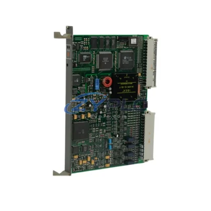
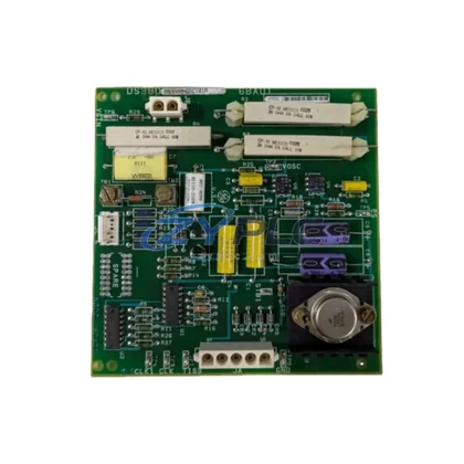
Allen-Bradley 1336-PB-SP6C 74101-181-51 Pre-Charge Power Board for 1336 Plus II
The Allen-Bradley 1336-PB-SP6C 74101-181-51 is a factory-engineered pre-charge power board designed as an integral component within the 1336 Plus II variable frequency drive platform. In modern industrial automation environments, a drive system is never a standalone device — it is a node within a layered control architecture that spans from the programmable logic controller at the top level down through I/O modules, communication gateways, power conditioning units, and ultimately to the motor and mechanical load. The 1336-PB-SP6C fulfills a critical role in this hierarchy: it governs the controlled energization of the DC bus capacitor bank during drive startup, preventing inrush current events that could destabilize upstream power distribution or trigger nuisance tripping of branch circuit protection devices. Understanding this board’s function within the broader system context is essential for engineers responsible for drive commissioning, predictive maintenance, and long-term architecture reliability.
Product Specification Table
| Parameter |
Specification |
| Part Number |
1336-PB-SP6C / 74101-181-51 |
| System Role |
Pre-Charge Power Board — DC Bus Inrush Control |
| Compatible Platform |
Allen-Bradley 1336 Plus II Variable Frequency Drive Series |
| Board Function |
Controls pre-charge relay sequencing and DC bus capacitor charging during power-up |
| Electrical Interface |
Interfaces with main power board, gate driver board, and control board within 1336 Plus II chassis |
| Communication Role |
Internal board-level signal coordination; supports drive-level DeviceNet and DPI communication architecture |
| Installation Environment |
Enclosed drive chassis; suitable for industrial panel environments per NEMA/IEC enclosure standards |
| Operating Temperature |
0°C to 50°C (drive chassis ambient) |
| Humidity |
5% to 95% non-condensing |
| Warranty |
warranty terms confirmed during quotation from date of shipment |
| Condition |
Tested, inspected, and verified functional prior to dispatch |
| Origin |
United States (Allen-Bradley / Rockwell Automation) |
System Compatibility Notes
The 1336-PB-SP6C does not operate in isolation. Its performance and reliability are directly tied to the integrity of every other board and module within the 1336 Plus II drive chassis and the wider automation system. At the drive level, the pre-charge board works in close coordination with the 1336-PB-SP6A main power board, which handles the primary rectification and DC bus distribution. The gate driver board — such as the 1336-BRF-SP5A — receives enable signals only after the pre-charge sequence has completed successfully, ensuring that IGBT switching does not begin until the bus voltage has stabilized. The 1336-L6E control board monitors pre-charge status through internal feedback loops and communicates drive state to the supervisory control layer.
At the control layer, a Allen-Bradley ControlLogix L7x series PLC or a CompactLogix L3x controller typically serves as the system master, issuing run/stop commands to the drive via a 1336-GM-1 DeviceNet communication module or through a 1203-USB DPI-to-USB gateway used during commissioning and diagnostics. The drive’s integration into the plant network relies on consistent communication timing, which is why the pre-charge board’s reliable startup sequencing is foundational — a failed or slow pre-charge event can generate fault codes that interrupt the entire production sequence managed by the PLC program.
On the power conditioning side, the 1336 Plus II is typically fed through a 1321-3R line reactor or an Allen-Bradley 1321-3RA isolation transformer, both of which work in tandem with the pre-charge circuit to limit dV/dt stress on the input rectifier bridge. In redundant drive architectures — common in water treatment pump stations, mining conveyor systems, and petrochemical compressor trains — a bypass contactor assembly and a secondary drive unit may be configured in parallel, making the pre-charge board’s consistent operation critical to seamless switchover. The 1336-BRF-SP2A snubber board and associated capacitor assemblies are also part of this power-layer ecosystem, and their condition directly affects the load seen by the pre-charge circuit during each startup cycle.
At the human-machine interface layer, operators interact with the drive system through a PanelView Plus 7 terminal connected via EtherNet/IP, where drive status, fault history, and pre-charge cycle counts can be monitored in real time. Maintenance engineers use Studio 5000 Logix Designer and DriveExecutive software to configure drive parameters, review fault logs, and validate that the pre-charge timing parameters align with the connected motor and load characteristics. This end-to-end system integration — from the power board level through to the HMI and SCADA layer — is what defines a well-engineered 1336 Plus II system deployment.
Industrial Application Notes
Manufacturing & Packaging Lines: In high-cycle automated packaging and assembly lines, drives are started and stopped dozens of times per shift. The 1336-PB-SP6C’s pre-charge function protects the DC bus capacitors from cumulative stress caused by repeated inrush events, extending the operational life of the entire drive unit and reducing unplanned downtime on production lines where mean time between failures is a key performance indicator.
Water & Wastewater Treatment: Pump drive systems in municipal water treatment facilities operate continuously, often in outdoor or semi-outdoor enclosures subject to temperature cycling. The pre-charge board ensures that after a power interruption — whether planned or caused by a grid event — the drive restarts in a controlled manner without stressing the motor windings or the upstream transformer. This is particularly important in systems where multiple 1336 Plus II drives share a common bus or a common MCC section.
Mining & Minerals Processing: Conveyor drives, crusher drives, and slurry pump drives in mining environments are subject to heavy load inertia and frequent emergency stops. The pre-charge circuit must handle the residual bus voltage present after a coast-to-stop event, and the 1336-PB-SP6C is engineered to manage this condition reliably, supporting safe restart sequences that comply with mine safety regulations and equipment protection requirements.
Oil, Gas & Petrochemical: In hazardous area installations where drives are mounted in pressurized or purged enclosures, the ability to restart a drive quickly and safely after a process upset is critical. The pre-charge board’s role in preventing bus overvoltage during restart makes it an essential component in compressor and pump drive systems where process continuity directly impacts plant throughput and safety.
Power Generation & Utilities: Auxiliary drive systems in power plants — including cooling water pumps, induced draft fans, and boiler feed pumps — rely on the 1336 Plus II platform for its proven reliability. The pre-charge board supports the controlled startup sequences required by plant operating procedures, and its warranty terms confirmed during quotation provides procurement teams with the assurance needed to maintain approved spare parts inventories.
Product Compatibility FAQ
Q1: Is the 1336-PB-SP6C 74101-181-51 compatible with all 1336 Plus II drive frame sizes, and how do I confirm fitment before installation?
The 1336-PB-SP6C is designed for specific frame sizes within the 1336 Plus II series, typically associated with mid-range horsepower ratings. To confirm compatibility, cross-reference the drive’s catalog number and firmware revision against the Allen-Bradley 1336 Plus II spare parts cross-reference guide (publication 1336 PLUS II-6.5). The board’s 74101-181-51 assembly number is the definitive identifier for procurement. If you are replacing a failed board, photograph the existing board’s label and compare the assembly number before ordering. Our team can assist with compatibility verification prior to shipment under our system integration support service.
Q2: What commissioning steps are required after replacing the pre-charge power board, and are there parameter settings that need to be verified?
After installing the 1336-PB-SP6C, the drive should be powered up with the motor disconnected for an initial bus charge test. Monitor the DC bus voltage using the drive’s diagnostic display or via DriveExecutive software connected through the 1203-USB gateway. Verify that the pre-charge relay engages and disengages at the correct bus voltage thresholds as defined in the drive’s parameter set (typically Parameters 1–10 in the 1336 Plus II parameter group). No board-specific parameter programming is required, as the pre-charge timing is hardware-defined. However, confirm that the drive’s fault log is clear and that no pre-charge fault codes (F2, F12) are present before reconnecting the motor load.
Q3: What does the warranty terms confirmed during quotation cover, and what is the process for a warranty claim if the board fails after installation?
The warranty terms confirmed during quotation covers manufacturing defects and functional failures under normal operating conditions from the date of shipment. It does not cover damage caused by incorrect installation, overvoltage events, contamination, or operation outside the drive’s rated environmental specifications. To initiate a warranty claim, contact our support team at plc.sales@zyplc.com or +86 19859288691 with your order number, installation date, and a description of the failure mode. We will arrange for return shipment and provide a replacement or repair within the agreed service timeline. Our system integration support team can also assist with root cause analysis to prevent recurrence.