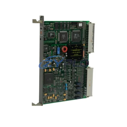
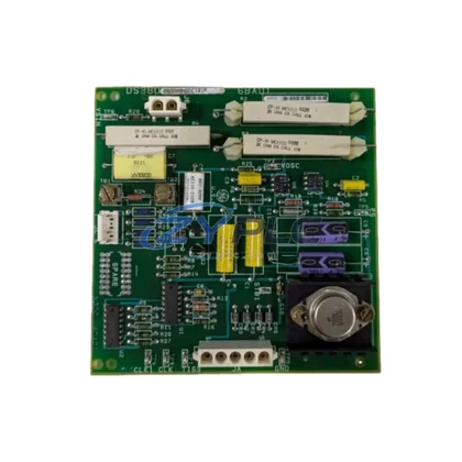
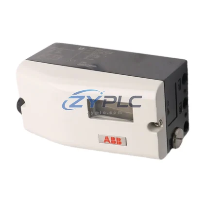
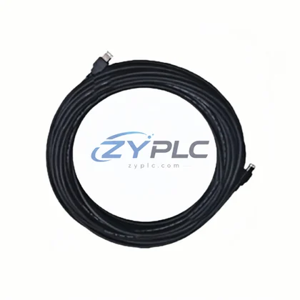
Bently Nevada 190501-13-00-01 Velocity Transducer for Velomitor CT Automation
The Bently Nevada 190501-13-00-01 Velomitor CT is a high-performance velocity transducer engineered for continuous vibration monitoring in demanding industrial environments. As factories and process plants push toward leaner energy profiles and higher equipment utilization, the 190501-13-00-01 plays a pivotal role in the feedback loop that keeps rotating machinery running at peak efficiency. By delivering accurate, real-time velocity signals directly to the control and protection system, this transducer enables operators to detect mechanical anomalies before they escalate into unplanned downtime — reducing both unplanned downtime and maintenance costs simultaneously.
Unlike passive monitoring approaches, the Velomitor CT integrates seamlessly into active maintenance planning architectures. Its wide-band frequency response captures the full spectrum of mechanical vibration signatures, from low-speed compressors to high-speed turbines, giving the plant’s condition monitoring platform the data resolution needed to distinguish between normal operational vibration and early-stage bearing wear, rotor imbalance, or misalignment. Each of these fault modes, if left undetected, forces the drive system to compensate through increased torque demand — directly inflating operating load at the motor and variable frequency drive level.
Product Specification Table
| Parameter |
Specification / Value |
| SKU / Part Number |
190501-13-00-01 |
| Product Series |
Velomitor CT |
| Transducer Type |
Velocity (Seismic) |
| Frequency Range |
Approx. 2 Hz – 1,000 Hz |
| Output Signal |
Analog voltage proportional to velocity |
| Power Consumption |
Low-draw, loop-powered design |
| Operating Efficiency |
High signal fidelity with minimal self-heating |
| Compatible Systems |
Bently Nevada 3500 Series, System 1 Software |
| Application Environment |
Rotating machinery, turbines, compressors, pumps, motors |
| Maintenance Value |
Enables predictive maintenance, reduces unplanned stops and excess drive load |
| Warranty |
warranty terms confirmed during quotation |
| Origin |
United States |
System Compatibility and Application
In a fully integrated industrial maintenance planning system, the 190501-13-00-01 Velomitor CT does not operate in isolation. It functions as the sensing front-end of a layered architecture that spans from field-level signal acquisition through to supervisory energy analytics. At the protection layer, the transducer feeds velocity data into the Bently Nevada 3500/42M Proximitor/Seismic Monitor, which processes the signal and triggers alarms or shutdowns when vibration thresholds are exceeded. This prevents catastrophic failures that would otherwise force emergency restarts — events that consume disproportionate amounts of energy and stress the entire drive chain.
On the drive side, the vibration data captured by the 190501-13-00-01 informs the tuning of variable frequency drives such as the Rockwell Automation PowerFlex 755 or ABB ACS880, which regulate motor speed to match actual load demand. When the transducer detects elevated vibration at a specific frequency band, the control system can instruct the VFD to adjust output frequency, reducing mechanical stress and lowering energy draw simultaneously. This closed-loop interaction between the Velomitor CT, the protection monitor, and the drive controller is the foundation of maintenance-focused motor management.
At the I/O and communication layer, the analog output of the 190501-13-00-01 is typically wired into a Bently Nevada 3500/20 Rack Interface Module or connected through a PROFIBUS or Modbus RTU gateway to the plant’s distributed control system (DCS) or programmable logic controller (PLC). Integration with platforms such as the Siemens S7-1500 PLC or the Rockwell ControlLogix L85E allows the vibration signal to be correlated with process variables — flow rate, pressure, temperature — enabling the maintenance planning system to build a comprehensive picture of equipment health and efficiency.
For human-machine interface visibility, operators monitoring the production line through a Siemens SIMATIC HMI TP1500 or a Wonderware InTouch SCADA panel can view real-time vibration trends alongside operating load KPIs. When the 190501-13-00-01 reports a rising velocity amplitude on a critical pump, the operator can proactively schedule maintenance during a planned production window rather than reacting to an unplanned trip — preserving production throughput and avoiding the energy penalty of emergency restarts and re-ramp sequences.
Power quality monitoring instruments, such as the Schneider Electric PowerLogic ION9000 power meter, complement the vibration data by tracking harmonic distortion and power factor at the motor feeder level. A deteriorating bearing detected by the Velomitor CT often correlates with increased harmonic content in the motor current, and cross-referencing both data streams allows the energy team to quantify the exact efficiency loss attributable to the mechanical fault — making the business case for timely intervention clear and data-driven.
Maintenance and Replacement Notes
In continuous process industries — petrochemical plants, paper mills, steel rolling lines, and water treatment facilities — rotating equipment accounts for the majority of electrical operating load. Pumps, fans, compressors, and agitators driven by induction motors are the primary energy consumers, and their efficiency is directly tied to mechanical condition. The Bently Nevada 190501-13-00-01 Velomitor CT addresses this challenge by providing the high-fidelity vibration signal that condition monitoring and maintenance planning systems depend on to make intelligent decisions.
Consider a centrifugal pump operating with a developing impeller imbalance. Without vibration monitoring, the imbalance goes undetected, the pump operates at reduced hydraulic efficiency, the motor draws abnormal load to maintain flow, and the variable frequency drive compensates by increasing output — all of which translate directly into higher operating load per unit of process output. With the 190501-13-00-01 installed on the pump bearing housing, the Bently Nevada 3500 system detects the imbalance signature early. Maintenance is scheduled, the impeller is rebalanced during a planned outage, and the pump returns to its design efficiency curve — reducing operating load by a measurable percentage and extending bearing life.
On high-speed turbine trains, the Velomitor CT’s broad frequency response captures both sub-synchronous and super-synchronous vibration components that indicate rotor instability or blade resonance. Early detection of these conditions allows the control system to modulate steam or gas flow through the turbine governor, reducing mechanical loading and preventing the efficiency losses associated with operating in a vibration-amplified condition. The result is a turbine that runs closer to its design efficiency point for longer periods between overhauls.
From a production line rhythm perspective, unplanned equipment stops caused by vibration-related failures disrupt the entire production sequence. Each emergency stop triggers a re-ramp sequence that consumes excess energy as motors accelerate back to operating speed and process conditions are re-established. By enabling predictive maintenance through accurate vibration measurement, the 190501-13-00-01 helps production planners maintain consistent line throughput, reduce the frequency of energy-intensive restart cycles, and lower the overall energy intensity of the production process.
All units of the Bently Nevada 190501-13-00-01 supplied by ZYPLC are sourced from verified supply channels, subjected to outgoing functional testing prior to shipment, and covered by a warranty terms confirmed during quotation. Stock availability is maintained to support both planned maintenance schedules and urgent replacement requirements, minimizing the lead time between fault detection and corrective action.
Product Sourcing FAQ
Q1: How does the 190501-13-00-01 Velomitor CT contribute to operational stability in a motor-driven system?
By providing accurate, real-time vibration velocity data, the Velomitor CT enables the condition monitoring system to detect mechanical faults — such as imbalance, misalignment, and bearing wear — before they cause efficiency losses at the motor and drive level. Early fault detection allows maintenance to be performed proactively, keeping the motor and driven equipment operating at their design efficiency points and reducing unplanned downtime risk.
Q2: Is the 190501-13-00-01 compatible with the Bently Nevada 3500 Series monitoring system?
Yes. The 190501-13-00-01 Velomitor CT is designed for use with the Bently Nevada 3500 Series machinery protection system, including the 3500/42M Proximitor/Seismic Monitor. Its analog output is compatible with the signal conditioning inputs of the 3500 rack, and the transducer can also be integrated into System 1 software for advanced diagnostics and energy performance trending.
Q3: Can this transducer replace other Velomitor CT variants, and what should be verified before substitution?
The 190501-13-00-01 is a specific configuration within the Velomitor CT product family. Before substituting it for another variant, verify that the connector type, cable length, sensitivity rating, and mounting thread specification match the requirements of the installation. ZYPLC’s technical team can assist with cross-reference verification to ensure the replacement is fully compatible with the existing monitoring architecture.
Q4: What does the warranty terms confirmed during quotation cover, and what is the testing process before shipment?
The warranty terms confirmed during quotation covers defects in materials and workmanship under normal operating conditions. Prior to shipment, each unit undergoes functional testing to verify output signal integrity and sensitivity within specification. Units that do not meet the acceptance criteria are not shipped. The warranty period begins from the date of shipment, and ZYPLC provides support for warranty claims including replacement or repair as appropriate.