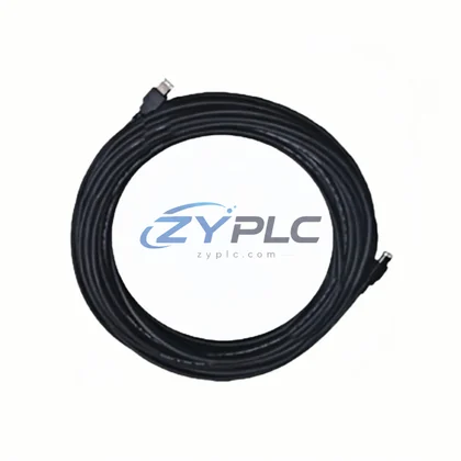
Bently Nevada 330130-045-00-00 Extension Cable for 3300 Series: Compatibility and Replacement Notes
In a fully integrated machinery protection and condition monitoring architecture, signal integrity between the proximity probe, extension cable, and signal conditioning module is not a peripheral concern — it is the foundation of measurement accuracy. The Bently Nevada 330130-045-00-00 is a system-compatible extension cable engineered specifically for the 3300 Series vibration monitoring platform, providing the critical electrical bridge between the proximity probe tip and the rack-mounted monitor. Its role within the control system hierarchy spans the field instrumentation layer and the signal acquisition layer, directly influencing the quality of data processed at the I/O and control layers above.
Unlike generic cabling solutions, the 330130-045-00-00 is designed to maintain the precise impedance, capacitance, and shielding characteristics required by Bently Nevada’s eddy-current measurement chain. When deployed alongside compatible proximity probes such as the 330103-00-06-10-02-00 or 330104-00-06-10-02-00, and terminated into a 3300/16 Monitor or 3300/20 Monitor installed in a standard 3300 Series rack, the cable ensures that the analog signal path remains free of noise, ground loops, and impedance mismatches that would otherwise corrupt vibration amplitude and phase readings. This level of signal fidelity is non-negotiable in rotating machinery protection applications where a 1 mil measurement error can be the difference between a safe shutdown and an undetected fault progression.
Product Specification Table
| Parameter |
Specification |
| Part Number |
330130-045-00-00 |
| Brand |
Bently Nevada |
| Series |
3300 Series Proximity Transducer System |
| System Role |
Extension Cable — Field Instrumentation to Monitor Interface |
| Cable Length |
45 ft (13.7 m) |
| Compatible Probe Types |
3300 Series 8 mm Proximity Probes |
| Electrical Characteristic |
Matched impedance and capacitance for eddy-current measurement chain |
| Shielding |
Double-shielded coaxial construction for EMI/RFI rejection |
| Connector Type |
Standard Bently Nevada coaxial connectors (probe end / monitor end) |
| Operating Temperature |
-40°C to +85°C |
| Installation Environment |
Industrial — suitable for turbine halls, compressor stations, pump skids |
| Communication Layer |
Analog signal (4–20 mA / voltage output to monitor) |
| Rack Compatibility |
3300 Series Monitor Rack, 3500 Series Rack (with adapter) |
| Warranty |
warranty terms confirmed during quotation — covers manufacturing defects and electrical performance |
System Compatibility Notes
The 330130-045-00-00 extension cable does not operate in isolation. Its value is realized only when it is correctly positioned within a coordinated measurement chain and integrated into a broader machinery protection architecture. In a typical turbine or compressor monitoring installation, the signal path begins at the 330103-00-06-10-02-00 Proximity Probe mounted at the bearing journal, passes through the 330130-045-00-00 extension cable routed through conduit or cable tray, and terminates at the 3300/16 or 3300/20 Vibration Monitor housed in the rack enclosure.
At the rack level, the monitor communicates processed vibration data — including gap voltage, 1X amplitude, 2X amplitude, and overall vibration — to the 3500/22M Transient Data Interface or directly to the plant DCS via a 3500/92 Communication Gateway supporting Modbus RTU or Ethernet/IP protocols. This data is then consumed by the System 1 Condition Monitoring Software running on the plant historian server, where trend analysis, alarm management, and predictive maintenance decisions are made.
Within the same control cabinet, the rack is powered by a 3300/05 Power Supply or a redundant pair of 3500/15 Power Supplies, ensuring that voltage fluctuations at the field level do not propagate into the measurement chain. Terminal blocks such as the 3300 Series I/O Module Terminal Blocks provide the physical interface between field wiring and the monitor inputs, while the 3300 Series Rack Backplane distributes power and communication signals across all installed monitor cards. For installations requiring redundant measurement — common in API 670-compliant machinery protection systems — a second measurement chain using an identical 330130-045-00-00 cable and probe assembly is installed at 90° to the primary, feeding a redundant monitor channel within the same rack.
The 330130-045-00-00 is also compatible with installations that are transitioning from legacy 3300 Series racks to the newer 3500 Series Rack platform. In such hybrid architectures, the extension cable can be retained while the monitor cards are upgraded, reducing the cost and complexity of field rewiring during system modernization projects.
Industrial Application Notes
The 330130-045-00-00 extension cable finds application across a wide range of process industries where rotating machinery protection is mandated by safety standards or operational reliability requirements.
In power generation facilities — including gas turbines, steam turbines, and hydro generators — the cable is deployed as part of the shaft vibration and eccentricity monitoring system. Turbine OEMs and EPC contractors specify Bently Nevada 3300 Series transducer systems as the standard measurement chain for new installations and life-extension projects, making the 330130-045-00-00 a long-term stocking requirement for plant maintenance teams.
In petrochemical and refinery applications, the cable is used on centrifugal compressors, expanders, and large pump trains where API 670 compliance is required. The double-shielded construction provides reliable signal transmission in environments with high levels of electromagnetic interference from variable frequency drives, switchgear, and high-voltage bus systems.
In water treatment and municipal infrastructure plants, the cable supports vibration monitoring on large vertical turbine pumps and blower trains, where early detection of bearing wear or rotor imbalance prevents costly unplanned outages. The wide operating temperature range makes it suitable for both indoor pump houses and outdoor installations in tropical or arctic climates.
In mining and minerals processing operations, the 330130-045-00-00 is used on SAG mill pinion bearings, crusher drives, and slurry pump trains. The rugged coaxial construction withstands the vibration, dust, and moisture exposure typical of these environments, while the 45 ft cable length accommodates the large physical separation between bearing housings and control room enclosures common in mining plant layouts.
In metallurgical and steel mill applications, the cable supports continuous caster roll monitoring, rolling mill drive train protection, and blast furnace blower monitoring — all environments where the consequences of undetected machinery faults are severe in terms of both safety and production loss.
Product Compatibility FAQ
Q1: Is the 330130-045-00-00 compatible with both 3300 Series and 3500 Series monitor racks?
The 330130-045-00-00 is natively designed for the 3300 Series proximity transducer system. It is fully compatible with 3300/16 and 3300/20 monitors. For use with 3500 Series monitors, compatibility depends on the specific monitor card and connector configuration — in many hybrid upgrade projects, the existing 3300 Series extension cables are retained and connected to 3500 Series I/O modules via appropriate adapter assemblies. Always verify the connector type and electrical specifications against the target monitor card datasheet before installation.
Q2: How does the extension cable affect overall system calibration and what should be verified during commissioning?
The extension cable is a calibrated component of the eddy-current measurement chain. Its capacitance and impedance characteristics are matched to the probe and driver/monitor to achieve the correct sensitivity (typically 200 mV/mil or 7.87 V/mm). During commissioning, the gap voltage should be set with the complete cable assembly installed — probe, extension cable, and monitor — to ensure the calibration reflects actual field conditions. Any substitution of a non-matched cable will shift the calibration curve and introduce measurement error. The warranty terms confirmed during quotation covers the cable’s electrical performance within the specified measurement chain configuration.
Q3: What is the recommended maintenance strategy for extension cables in long-term machinery protection installations?
Extension cables should be inspected during each planned maintenance outage for physical damage, connector corrosion, and shield continuity. The gap voltage reading at the monitor provides a continuous in-service health indicator — a drift in gap voltage without a corresponding change in shaft position indicates cable degradation or connector contamination. For critical machinery, it is recommended to maintain one spare 330130-045-00-00 per measurement point in the plant warehouse. The warranty terms confirmed during quotation provides coverage for the initial service period, and ZYPLC maintains availability confirmed by RFQ availability to support rapid replacement requirements across all major industrial regions.