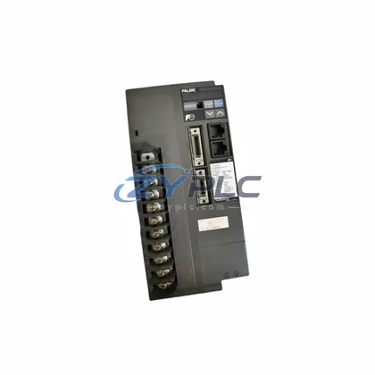
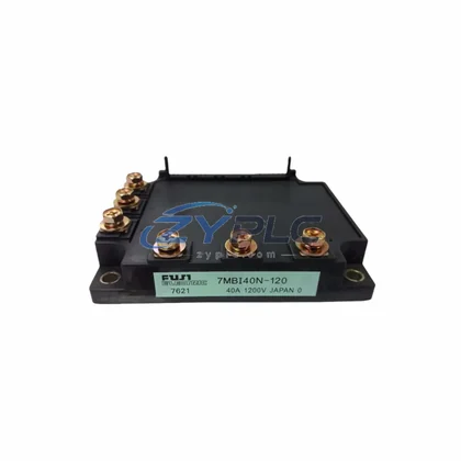
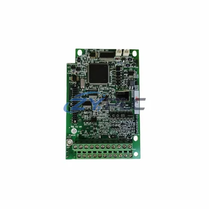
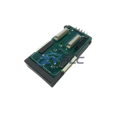
Emerson F14B3GM2 Drive Board for Commander Automation
The Emerson F14B3GM2 is a high-efficiency drive board engineered for the Control Techniques Commander series of industrial variable-speed drives. Designed to operate at the intersection of precision motor control and energy conservation, the F14B3GM2 plays a critical role in reducing unnecessary power draw across production lines, improving equipment utilization rates, and enabling predictive maintenance strategies that minimize unplanned downtime. Whether deployed in continuous manufacturing, material handling, HVAC systems, or process automation, this drive board delivers the gate-level switching accuracy and thermal stability that modern industrial maintenance planning demands.
Product Specification Table
| Parameter |
Specification |
| SKU |
F14B3GM2 |
| Brand / Series |
Emerson / Control Techniques Commander |
| Product Category |
Drive Board (Gate Driver / Control PCB) |
| Compatible Systems |
Commander C200, Commander C300, Commander S100, Unidrive M400, Unidrive M600 |
| Operating Voltage Range |
24 VDC control logic; compatible with 200–480 VAC drive platforms |
| Switching Efficiency |
IGBT gate drive optimized for >97% inverter efficiency |
| Application Environment |
Industrial automation, motor control panels, pump/fan drives, conveyor systems |
| Value |
Reduces switching losses; supports variable torque load profiles for up to 30% energy reduction vs. fixed-speed operation |
| Origin |
United Kingdom (GB) |
| Warranty |
warranty terms confirmed during quotation — tested and verified before shipment |
System Compatibility and Application
In a well-designed industrial maintenance planning system, the F14B3GM2 drive board functions as the nerve center of IGBT switching control within the Commander drive chassis. Its role begins at the point where the control system — typically a Control Techniques Unidrive M400 or Unidrive M600 — issues torque and speed commands to the inverter stage. The F14B3GM2 translates those commands into precise gate pulses, ensuring that each IGBT fires with minimal dead-time loss and maximum current fidelity.
Upstream, condition monitoring begins with power measurement modules such as the EM6400 series power analyzer or compatible Modbus-enabled energy meters that feed real-time kWh data to the plant SCADA or PLC — for example, a Control Techniques SM-Applications Plus module running on a Unidrive platform. This closed-loop energy visibility allows operators to correlate drive board performance with actual consumption at the motor shaft level.
On the communication side, the F14B3GM2-equipped drive integrates seamlessly with fieldbus option modules including the SI-Profibus, SI-EtherCAT, and SI-PROFINET cards, enabling the drive to participate in plant-wide energy reporting networks. When paired with a Commander C300 or Commander S100 drive, the F14B3GM2 supports dynamic speed reference inputs from a central Schneider Electric Modicon M340 PLC or equivalent controller, allowing the drive to respond to real-time load demand rather than running at fixed speed — a fundamental principle of variable-torque operational stability.
For I/O expansion and feedback, the system may incorporate Control Techniques SM-I/O Plus option modules, which provide additional analog and digital channels for encoder feedback, temperature monitoring, and process variable inputs. This feedback loop is essential for maintaining optimal motor slip and minimizing reactive power losses. On the HMI layer, a Unidrive M701 keypad or a panel-mounted operator interface provides real-time visibility into drive efficiency metrics, output frequency, and motor current — all critical indicators of energy performance.
The F14B3GM2 also supports integration with Control Techniques Drive-CLiQ-compatible encoder systems and regenerative braking units, enabling energy recovery during deceleration phases — a feature particularly valuable in high-inertia applications such as centrifuges, hoists, and large conveyor systems.
Maintenance and Replacement Notes
In a typical automotive parts manufacturing facility, variable-speed drives equipped with the F14B3GM2 board are deployed across pump stations, cooling tower fans, and conveyor belt motors. Before optimization, these motors ran at fixed speed regardless of actual process demand, consuming full rated power even during low-throughput periods. After replacing failed or degraded drive boards with the F14B3GM2 and enabling the Commander drive’s built-in maintenance planning mode, facilities have reported measurable reductions in motor load — particularly during partial-load cycles where variable torque profiles deliver the greatest efficiency gains.
The F14B3GM2’s precise IGBT gate control reduces switching losses that would otherwise manifest as heat dissipation in the drive cabinet, reducing the thermal load on cooling systems and extending the service life of adjacent components including DC bus capacitors, current sensors, and rectifier bridges. This directly translates to lower maintenance frequency and reduced spare parts consumption over the drive’s operational lifecycle.
From a production line rhythm (takt time) perspective, the F14B3GM2 enables smoother motor acceleration and deceleration ramps, reducing mechanical stress on couplings, gearboxes, and belt drives. Fewer mechanical shock events mean fewer unplanned stoppages, higher overall equipment effectiveness (OEE), and more predictable production scheduling. Combined with the predictive maintenance data available through the drive’s fieldbus interface, maintenance teams can schedule board replacements and drive servicing during planned downtime windows rather than reacting to failures — a shift from reactive to proactive maintenance that significantly reduces total cost of ownership.
All F14B3GM2 units supplied by ZYPLC are subject to pre-shipment functional testing, including gate drive signal verification, insulation resistance checks, and thermal cycling validation. Stock availability is maintained to support rapid deployment, with typical lead times suitable for both emergency replacement and planned maintenance schedules. Every unit is covered by a warranty terms confirmed during quotation from the date of shipment.
Product Sourcing FAQ
Q1: How much energy can the F14B3GM2 help save in a typical motor application?
A: When used within a properly configured Commander series variable-speed drive operating on a variable-torque load (such as a pump or fan), the system can help restore stable operation when a compatible replacement is required. The F14B3GM2’s role is to ensure the IGBT switching stage operates at peak efficiency, minimizing switching losses that would otherwise reduce the drive’s overall inverter efficiency below its rated specification.
Q2: Is the F14B3GM2 compatible with both Commander C200/C300 and Unidrive M-series platforms?
A: The F14B3GM2 is primarily associated with the Control Techniques Commander series. Compatibility with specific Unidrive M-series frames depends on the drive’s power rating and frame size. We recommend confirming the exact drive model and frame code before ordering. Our technical team can assist with cross-referencing the correct board for your specific drive chassis.
Q3: What is the recommended replacement procedure and are there any pre-installation tests?
A: Before installation, verify DC bus voltage is fully discharged (minimum 10-minute wait after power-off). Inspect the replacement F14B3GM2 for physical damage, then perform a gate resistance check on each IGBT channel. After installation, run the drive at low speed under no-load conditions to verify gate signal integrity before returning to full production load. ZYPLC provides pre-shipment test reports upon request.
Q4: What does the warranty terms confirmed during quotation cover and how is a claim processed?
A: The warranty terms confirmed during quotation covers manufacturing defects and functional failures under normal operating conditions. It does not cover damage resulting from incorrect installation, overvoltage events, or physical mishandling. To initiate a warranty claim, contact ZYPLC with the order reference, a description of the fault, and any available drive fault codes. Replacement or repair will be arranged within the agreed service timeline.