Siemens A1A10000432.02M Gate Board for ROBICON: Compatibility and Replacement Notes
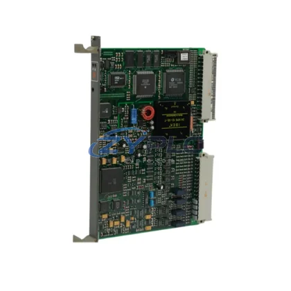
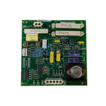
The Siemens A1A10000432.02M is a precision-engineered gate board designed for deployment within the ROBICON medium-voltage drive platform — one of Siemens’ most robust and widely adopted variable frequency drive (VFD) architectures in heavy industrial environments. Rather than functioning as a standalone component, this gate board occupies a critical position within a layered automation hierarchy, serving as the bridge between the control layer’s command signals and the power layer’s switching execution. Understanding its role demands a systems-level perspective that spans the control layer, I/O layer, network layer, power layer, human-machine interface layer, and execution layer simultaneously.
In a complete ROBICON drive system, the A1A10000432.02M gate board receives firing pulse signals from the drive’s central control board — typically a unit such as the Siemens A1A10000431 Master Control Board or equivalent ROBICON control card — and translates those signals into precise gate trigger pulses for the IGBT or GTO thyristor power modules. This signal chain is fundamental to the drive’s ability to regulate motor speed, torque, and power factor with the accuracy demanded by process-critical applications. Any degradation in gate signal timing or amplitude directly impacts drive output quality, making the integrity of this board essential to overall system performance.
From a system architecture standpoint, the A1A10000432.02M interfaces with multiple upstream and downstream components. On the upstream side, it receives logic-level control signals from the drive’s main processor board, which itself communicates with the plant’s distributed control system (DCS) or programmable logic controller (PLC) via fieldbus protocols such as PROFIBUS-DP or Modbus RTU. On the downstream side, the gate board drives the gate resistors and isolation circuits connected directly to the power semiconductor modules — components such as the Siemens A1A10000450 Power Cell or equivalent ROBICON power stack assemblies. This tight coupling between control intelligence and power execution is what makes the gate board a linchpin of system consistency.
Product Specification Table
| Parameter |
Specification |
| Part Number / SKU |
A1A10000432.02M |
| Brand |
Siemens |
| Series / Platform |
ROBICON Medium-Voltage Drive |
| Product Type |
Gate Board (Gate Driver Card) |
| System Role |
Gate pulse generation and isolation for power semiconductor modules |
| Compatible Power Devices |
IGBT modules / GTO thyristors within ROBICON power cells |
| Signal Interface |
Logic-level gate trigger input from master control board |
| Isolation Method |
Optical isolation (fiber optic or opto-coupler, per ROBICON standard) |
| Operating Voltage |
Per ROBICON drive cell specification (typically 24 VDC logic supply) |
| Communication Compatibility |
PROFIBUS-DP, Modbus RTU (via upstream control board) |
| Mounting |
Direct board-level installation within ROBICON power cell chassis |
| Operating Temperature |
0°C to +55°C (standard industrial enclosure) |
| Origin |
Germany |
| Warranty |
warranty terms confirmed during quotation (ZYPLC) |
| Availability |
RFQ Available — global shipping available |
System Compatibility Notes
The A1A10000432.02M gate board achieves its full value only when considered within the broader ROBICON system architecture. A typical ROBICON medium-voltage drive installation integrates numerous coordinated components across multiple functional layers. At the control layer, the Siemens A1A10000431 Master Control Board (or equivalent ROBICON CPU card) orchestrates all drive functions, generating the PWM firing sequences that the gate board must faithfully execute. Alongside it, the Siemens A1A10000433 Fiber Optic Interface Board provides the optical signal transmission path that carries gate commands from the control board to the gate board with complete electrical isolation — a critical safety and noise-immunity feature in high-voltage environments.
At the power layer, the gate board works in direct coordination with the ROBICON A1A10000450 Power Cell Assembly, where each cell contains its own set of power semiconductors requiring individual gate drive circuits. In multi-cell ROBICON configurations — common in 3.3 kV, 6.6 kV, and 11 kV drive systems — multiple A1A10000432.02M gate boards operate in parallel, each assigned to a specific power cell, ensuring synchronized switching across all cells for clean, low-harmonic output waveforms. The Siemens A1A10000460 Cell Bypass Module may also be present in redundant architectures, allowing a failed power cell to be bypassed while the drive continues operating at reduced capacity — a feature that depends on the gate board’s reliable fault detection and reporting capability.
At the power supply layer, the Siemens A1A10000420 Auxiliary Power Supply Board provides the isolated DC voltages required by the gate board’s logic and driver circuits. Stable auxiliary power is non-negotiable: voltage ripple or dropout at this layer directly causes gate misfires, which manifest as overcurrent trips or drive faults at the system level. At the I/O and monitoring layer, the Siemens A1A10000440 Analog I/O Board collects temperature, current, and voltage feedback from the power cells, feeding this data back to the master control board for real-time protection and adaptive control. The gate board’s fault output signals are part of this feedback loop, enabling the control system to respond to gate driver failures within microseconds.
At the human-machine interface layer, operators interact with the ROBICON drive through a Siemens OP7 or OP17 operator panel, or through a SIMATIC HMI terminal connected via PROFIBUS. The gate board’s operational status — including fault codes, firing pulse confirmation, and thermal warnings — is surfaced through this interface, giving maintenance engineers the visibility needed for rapid diagnosis. At the network layer, the drive communicates with the plant DCS or SCADA system via a Siemens CP 342-5 PROFIBUS communication processor or equivalent gateway module, enabling remote monitoring and parameter adjustment without interrupting production.
Industrial Application Notes
The Siemens A1A10000432.02M gate board finds application across a wide range of heavy industrial sectors where medium-voltage variable speed drives are essential to process efficiency and reliability.
In mining and mineral processing, ROBICON drives equipped with this gate board control large ball mills, SAG mills, conveyor drives, and slurry pumps. The ability to soft-start multi-megawatt motors without mechanical shock extends equipment life and reduces maintenance intervals. The gate board’s precise firing control ensures smooth torque delivery even under highly variable load conditions typical of ore processing.
In oil and gas and petrochemical facilities, ROBICON drives manage compressor trains, pipeline pumps, and cooling tower fans in hazardous area installations. The multi-cell architecture’s inherent redundancy — supported by the gate board’s per-cell fault isolation — means that a single cell failure does not cause a full process shutdown, a critical advantage in continuous-process plants where unplanned downtime carries enormous cost.
In power generation and utilities, including thermal power stations and hydroelectric plants, ROBICON drives with A1A10000432.02M gate boards control boiler feed pumps, induced draft fans, and forced draft fans. These applications demand the highest levels of drive reliability and harmonic performance, both of which depend directly on the gate board’s ability to generate clean, precisely timed firing pulses across all power cells simultaneously.
In water and wastewater treatment, large centrifugal pumps and blowers driven by ROBICON VFDs benefit from the gate board’s contribution to low total harmonic distortion (THD), protecting sensitive instrumentation and reducing transformer heating in facilities where power quality is tightly regulated.
In steel, aluminum, and metals processing, rolling mill drives and extruder drives require extremely fast torque response and precise speed regulation. The A1A10000432.02M gate board’s low-latency signal path between the control board and the power semiconductors is a key enabler of the dynamic performance these applications demand.
Product Compatibility FAQ
Q1: Is the A1A10000432.02M gate board compatible with all ROBICON drive variants, and how do I confirm compatibility before installation?
The A1A10000432.02M is designed for use within the Siemens ROBICON medium-voltage drive platform, specifically in configurations using the corresponding power cell and control board generation. Compatibility depends on the drive’s firmware version, power cell type, and control board revision. Before installation, cross-reference the drive’s bill of materials (BOM) and the gate board’s revision marking against the ROBICON system documentation. If the original gate board part number matches A1A10000432.02M exactly, direct replacement is confirmed. For adjacent revisions (e.g.,.01M or.03M), consult the ROBICON service manual or contact ZYPLC’s technical team for cross-reference verification. All units supplied by ZYPLC are tested for functional integrity prior to dispatch.
Q2: What are the recommended installation and commissioning steps to ensure the gate board integrates correctly into the existing ROBICON architecture?
Installation must be performed with the drive fully de-energized and locked out, with all power cell capacitors discharged per ROBICON safety procedures. The gate board should be seated firmly in its designated slot within the power cell chassis, with all fiber optic connectors and ribbon cable connections verified for correct orientation and secure seating. After installation, perform a low-voltage functional test using the ROBICON diagnostic software to confirm gate pulse transmission and reception before applying full medium voltage. Verify that the master control board recognizes the gate board and reports no fault codes. Document the installation date to initiate the warranty terms confirmed during quotation coverage period from ZYPLC.
Q3: What does the warranty terms confirmed during quotation from ZYPLC cover, and what long-term maintenance practices are recommended to maximize gate board service life?
ZYPLC’s warranty terms confirmed during quotation covers manufacturing defects and functional failures under normal operating conditions for a period of twelve months from the date of shipment. It does not cover damage resulting from incorrect installation, overvoltage events, contamination, or unauthorized modification. For long-term reliability, inspect the gate board annually for signs of thermal stress, solder joint cracking, or component discoloration. Ensure the power cell enclosure maintains adequate cooling airflow and that the auxiliary power supply voltage remains within specification. Keep a spare A1A10000432.02M gate board in inventory for critical drive applications — ZYPLC maintains stock for rapid global dispatch, minimizing exposure to extended lead times on this legacy ROBICON component.