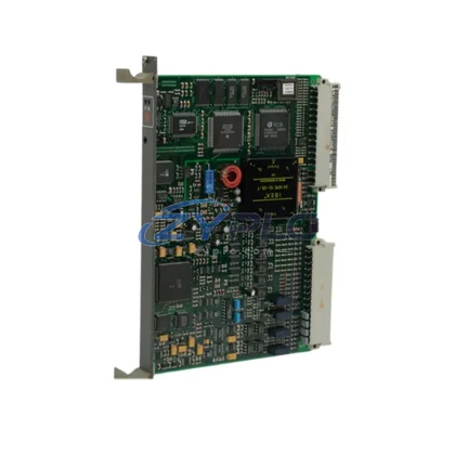
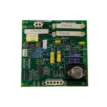
Siemens ROBICON F7E1A6G2 A1A0100275 Power Module for Perfect Harmony
The Siemens ROBICON F7E1A6G2 A1A0100275 is a cell-based power module engineered for deployment within the Perfect Harmony medium-voltage variable frequency drive (MV VFD) platform. In modern industrial automation, a drive system is never a standalone component — it is a node within a layered control architecture that spans the control layer, I/O layer, network layer, power layer, human-machine interface layer, and execution layer. This module is designed with that full-system perspective in mind, delivering the electrical performance, modular scalability, and long-term serviceability that demanding process industries require.
Within the Perfect Harmony architecture, each power cell module such as the A1A0100275 functions as a discrete H-bridge inverter unit. Multiple cells are stacked in series per phase to synthesize a near-sinusoidal output waveform, eliminating the need for output filters and reducing harmonic distortion to levels compliant with IEEE 519 standards. This cell-based topology is the foundation of the Perfect Harmony’s renowned reliability: a single cell fault does not cause a system trip. Instead, the drive’s cell bypass logic — integrated within the A1A1000001 master control board — automatically reconfigures the remaining cells to maintain motor operation at reduced voltage, enabling continued production while maintenance is scheduled.
Product Specification Table
| Parameter |
Specification |
| System Role |
H-Bridge Power Cell Module — Phase Output Stage |
| Compatible Platform |
Siemens ROBICON Perfect Harmony MV VFD Series |
| Cell Topology |
Single-phase H-bridge, series-connected per phase |
| Input Voltage (Cell) |
Typically 480–690 V AC (phase-isolated via drive transformer) |
| Output Voltage Contribution |
Per-cell PWM output, summed across series stack |
| Switching Technology |
IGBT-based PWM, low dV/dt output |
| Communication Interface |
Fiber optic link to A1A1000001 master control board |
| Cooling Method |
Forced air (integrated fan assembly) |
| Installation Environment |
Indoor, IP20 enclosure, -10°C to +40°C ambient |
| Bypass Capability |
Compatible with automatic cell bypass logic |
| Warranty |
warranty terms confirmed during quotation — Covered by ZYPLC |
System Compatibility Notes
The A1A0100275 power module does not operate in isolation. Its performance is inseparable from the coordinated function of every layer in the Perfect Harmony drive system. At the control layer, the A1A1000001 Master Control Board governs PWM gating signals, cell bypass decisions, and fault diagnostics. It communicates with each power cell via a dedicated fiber optic link, ensuring electrical isolation between the high-voltage power stage and the low-voltage control electronics — a critical safety and noise-immunity feature in medium-voltage environments.
The A1A0100274 Gate Driver Board interfaces directly with the IGBT switches inside each cell, translating the control board’s logic-level signals into the precise gate pulses required for reliable switching. Alongside it, the A1A0100276 Capacitor Bank Assembly provides the DC bus energy storage that smooths the rectified input and supports dynamic load transients. These three components — the power cell, gate driver, and capacitor bank — form the irreducible core of each cell module assembly.
At the power input layer, the Perfect Harmony Phase-Shifting Isolation Transformer (typically an 18-pulse or 36-pulse design) feeds each cell with a phase-displaced voltage, cancelling low-order harmonics at the utility connection point. This transformer is the upstream anchor of the entire cell stack, and its secondary winding count must match the number of series cells per phase in the installed drive configuration.
For process control integration, the drive communicates upstream via the A1A0100300 PROFIBUS DP Communication Module or the A1A0100310 Ethernet/IP Gateway, depending on the plant’s network architecture. These modules allow the drive to receive speed references, torque limits, and start/stop commands from a Siemens S7-400 or S7-300 series PLC, or from a DCS platform such as the Siemens SPPA-T3000. At the HMI layer, operators interact with the drive through the A1A0100350 Local Control Panel, which provides real-time cell status, fault history, and parameter access without requiring a laptop connection.
In redundant architecture designs — common in critical applications such as boiler feed pumps, compressor drives, and mine hoists — a hot-standby cell spare strategy is implemented. Maintaining a stock of A1A0100275 modules on-site reduces mean time to repair (MTTR) from days to hours, directly supporting production availability targets above 99.5%.
Industrial Application Notes
The A1A0100275 is deployed across a wide range of heavy industrial sectors where medium-voltage motor control is critical to process continuity.
In power generation and utilities, Perfect Harmony drives equipped with this cell module control induced draft fans, forced draft fans, and boiler feed pumps at ratings from 2.3 kV to 13.8 kV. The cell bypass capability is particularly valued in these applications, where an unplanned motor trip can trigger a full plant shutdown.
In petrochemical and refinery operations, the drive’s low harmonic output and transformer-isolated cell architecture meet the stringent electrical quality requirements of hazardous area installations. Compressor and pump drives running continuously at partial load benefit from the operational stability delivered by variable-speed operation, with the A1A0100275 cell module providing the switching precision needed for stable torque control across the full speed range.
In mining and minerals processing, conveyor drives, ball mill drives, and slurry pump systems demand high starting torque and robust fault tolerance. The series-cell architecture of the Perfect Harmony platform, anchored by modules like the A1A0100275, provides the torque linearity and cell redundancy that keep production running through individual component faults.
In water and wastewater treatment, large centrifugal pump drives benefit from the soft-start capability and precise flow control enabled by variable frequency operation. The A1A0100275 module’s compatibility with the drive’s automatic cell bypass ensures that pump stations maintain minimum flow requirements even during a partial drive fault condition.
In steel and metals manufacturing, rolling mill auxiliary drives and cooling system fans operate under highly variable load profiles. The Perfect Harmony’s multilevel output waveform, generated by the series stack of A1A0100275 cells, minimizes motor heating and bearing current issues that are common with conventional two-level inverter designs.
Product Compatibility FAQ
Q1: Is the A1A0100275 directly interchangeable with other Perfect Harmony cell modules, and what verification steps are required before installation?
The A1A0100275 is designed for specific Perfect Harmony drive configurations defined by the drive’s nameplate voltage, current rating, and cell count per phase. Before installation, engineers must verify that the replacement cell’s DC bus voltage rating, capacitor bank specification, and gate driver interface match the existing installed cells. The A1A1000001 master control board firmware version should also be confirmed compatible with the replacement cell hardware revision. ZYPLC provides pre-shipment testing documentation and a warranty terms confirmed during quotation on all supplied modules to support this verification process.
Q2: How does the cell bypass function interact with the A1A0100275 during a fault, and what is the impact on motor output?
When the master control board detects a fault in an A1A0100275 cell — via the fiber optic feedback link — it activates the bypass contactor for that cell, removing it from the series stack. The drive’s control algorithm then recalculates the modulation index for the remaining cells to maintain the best possible output voltage. Depending on the drive’s design margin and the number of cells per phase, the motor may continue operating at 80–95% of rated voltage, sufficient for most process loads. This system integration of bypass logic with real-time modulation adjustment is a defining feature of the Perfect Harmony architecture.
Q3: What are the recommended long-term maintenance practices for the A1A0100275 to maximize service life and support the warranty terms confirmed during quotation coverage?
Recommended maintenance includes annual inspection of the IGBT module for signs of thermal stress or discoloration, verification of the DC bus capacitor bank capacitance (replacement recommended at <80% of rated capacitance), cleaning of the cooling fan and heat sink to maintain rated airflow, and re-torquing of all bus bar connections to manufacturer specifications. Fiber optic connectors should be inspected for contamination. Maintaining a documented maintenance log supports warranty claims and provides the engineering history needed for predictive replacement planning. ZYPLC recommends stocking at least one spare A1A0100275 per drive system to minimize MTTR.
—