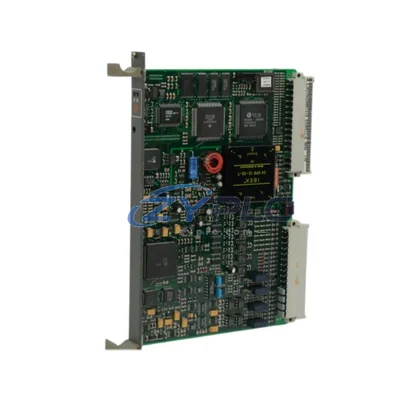
Thermal Dynamics PCB NO:7337 Pilot Arc PCB for Pak Series
The Thermal Dynamics PCB NO:7337 is a precision-engineered Pilot Arc PCB Assembly designed to occupy a critical position within the Pak Series plasma cutting control architecture. Rather than functioning as a standalone replacement component, this board is best understood as a system-level element — one that governs the initiation sequence, arc stability, and high-frequency pilot arc discharge that enables consistent, repeatable plasma cutting performance across demanding industrial environments. In layered automation systems where plasma cutting is integrated into broader manufacturing workflows, the reliability of the pilot arc initiation stage directly affects throughput, cut quality, and downstream process consistency.
Within the Pak Series control hierarchy, the PCB NO:7337 interfaces with the main power supply regulation circuitry, the torch lead assembly, and the high-frequency arc starter module. Its role is to manage the controlled release of pilot arc energy at the moment of torch ignition, ensuring that the transferred arc establishes cleanly without voltage spikes that could compromise sensitive upstream control electronics. This makes the board a foundational element in any Pak Series system where arc reliability and electromagnetic compatibility are engineering priorities.
Product Specification Table
| Parameter |
Specification |
| System Role |
Pilot Arc Initiation & Control PCB |
| Compatible Platform |
Thermal Dynamics Pak Series Plasma Systems |
| Part Number / SKU |
PCB NO:7337 |
| Board Function |
High-Frequency Pilot Arc Discharge Control |
| Electrical Interface |
Integrated with main power supply and HF starter circuit |
| Signal Compatibility |
Pak Series torch lead and control harness |
| Installation Environment |
Industrial plasma cutting enclosures, EMI-hardened cabinets |
| Communication Role |
Hardwired control signal integration within Pak Series architecture |
| Origin |
United States |
| Warranty |
— covers manufacturing defects and functional failure under normal operating conditions |
System Compatibility Notes
The PCB NO:7337 does not operate in isolation. Its performance is directly shaped by the quality and compatibility of every other component in the Pak Series control chain. In a fully coordinated system design, the pilot arc PCB works in concert with the Thermal Dynamics Pak 10 or Pak 12 power supply unit, which provides the regulated DC bus voltage that the pilot arc circuit draws upon during ignition. The high-frequency arc starter assembly — a separate module within the Pak Series enclosure — generates the initial ionization pulse that the PCB NO:7337 then manages and transitions into a stable transferred arc.
On the torch side, the Pak Series torch lead assembly and torch body must be matched to the PCB’s output characteristics. Mismatched torch leads with incorrect impedance profiles can cause erratic pilot arc behavior, which the PCB NO:7337 is not designed to compensate for. Ensuring that the consumable set — including the electrode, nozzle, and shield cup — is correctly specified for the cutting amperage range is equally important, as worn consumables increase the voltage demand on the pilot arc circuit and accelerate PCB stress cycles.
From a control integration perspective, the Thermal Dynamics remote control interface and any connected CNC height control unit communicate arc transfer status signals that originate from the pilot arc PCB’s feedback loop. In automated cutting cells where the plasma system is governed by a CNC controller or motion controller, the arc-on signal handshake depends on the PCB NO:7337 completing its initiation sequence within the expected timing window. Delays or failures at this stage propagate upstream as fault states in the motion controller, halting the cutting cycle and triggering alarm conditions.
For systems operating in redundant or high-availability configurations, maintaining a spare PCB NO:7337 alongside spare power supply regulation boards and HF starter modules is a standard engineering practice. This approach minimizes mean time to repair (MTTR) and ensures that a single board failure does not result in extended production downtime. The covering this assembly provides additional assurance during the initial commissioning and burn-in period of any Pak Series system integration project.
Industrial Application Notes
The Thermal Dynamics PCB NO:7337 finds its most demanding applications in environments where plasma cutting is embedded within multi-layer automation architectures. In metal fabrication and structural steel manufacturing, plasma cutting cells are often integrated with robotic material handling, automated nesting software, and MES-level production scheduling. In these environments, the pilot arc PCB must deliver consistent arc initiation across thousands of daily cutting cycles, with arc transfer times that fall within the tolerance windows expected by the upstream motion controller.
In shipbuilding and heavy plate cutting applications, the Pak Series systems equipped with PCB NO:7337 are deployed on large-format cutting tables where plate thicknesses and material compositions vary significantly across a single production shift. The pilot arc circuit must reliably initiate on mill-scale surfaces, painted steel, and galvanized material without requiring manual intervention or consumable changes between cuts.
In power generation and energy infrastructure maintenance environments, plasma cutting systems are used for in-situ repair and fabrication tasks where equipment uptime is critical. The availability of a warranted, system-compatible PCB NO:7337 with documented system integration support ensures that maintenance teams can restore cutting capability quickly without sourcing uncertainty.
For mining and mineral processing facilities, where plasma cutting supports equipment fabrication and structural repair in remote locations, the and global RFQ sourcing availability of the PCB NO:7337 reduce the logistical risk associated with component sourcing in geographically isolated operations. Similarly, in petrochemical plant maintenance and water treatment infrastructure projects, the board’s role in maintaining arc initiation reliability directly supports the safe and efficient execution of cutting and gouging tasks in regulated industrial environments.
Product Compatibility FAQ
Q1: Is the PCB NO:7337 compatible with all Pak Series plasma systems, and how do I confirm system compatibility before installation?
The PCB NO:7337 is designed for use within the Thermal Dynamics Pak Series plasma cutting platform. Compatibility should be confirmed by cross-referencing the part number against the specific Pak Series model’s service manual or bill of materials. Key compatibility indicators include the power supply voltage rating, the HF starter interface connector type, and the torch lead harness pinout. If you are integrating this board into a refurbished or field-modified Pak Series unit, contact our technical team with the full system serial number and model designation to confirm fit before installation.
Q2: What are the recommended installation and commissioning steps to ensure the PCB NO:7337 integrates correctly into an existing Pak Series control architecture?
Installation should be performed by a qualified plasma system technician with the system fully de-energized and capacitor banks discharged. After physical installation, verify all harness connections against the Pak Series wiring diagram, paying particular attention to the HF starter interface and the torch lead signal lines. Commission the board by performing a series of no-load pilot arc tests at minimum amperage before progressing to full cutting trials. Document arc transfer times and compare against baseline specifications. Any deviation exceeding 15% from the expected transfer window should be investigated before production use.
Q3: What does the cover for the PCB NO:7337, and how does it support long-term system maintenance planning?
The covers manufacturing defects and functional failures arising under normal operating conditions as defined by the Thermal Dynamics Pak Series application guidelines. It does not cover damage resulting from incorrect installation, operation outside rated parameters, consumable-related arc instability, or physical damage. For long-term maintenance planning, the warranty period provides a structured assurance window during which any latent manufacturing defects will manifest and be addressed at no additional cost. We recommend maintaining a documented commissioning record and operating log for each PCB NO:7337 installation to support any warranty assessment process.
—